
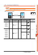
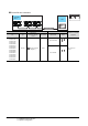
Specifications


11 - 10
11. CONNECTION TO GE PLC
11.3 Connection Diagram
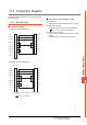
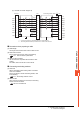
11.3.2 RS-422 cable
Connection diagram
(1) RS-422 connection diagram 1)
*1 Connect FG grounding to the appropriate part of a cable shield line.
*2 A terminating resistor should be connected to communication module at a terminal station.
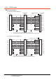
(2) RS-422 connection diagram 2)
*1 Connect FG grounding to the appropriate part of a cable shield line.
*2 Terminating resistor should be provided for a PLC which will be a terminal.
GOT side
Communication
Module
Communication
Module
SDA
SDB
RDA
RDB
SG
RSA
CSA
RSB
CSB
TERM
RD(B’)
RD(A’)
SD(B)
SD(A)
0V
RTS(A)
CTS(A’)
RTS(B)
CTS(B’)
SHLD
1
6
2
7
5
3
4
8
9
24
25
13
21
9
7
10
11
22
23
1
TERM
RD(B’)
RD(A’)
SD(B)
SD(A)
0V
RTS(A)
CTS(A’)
RTS(B)
CTS(B’)
SHLD
24
25
13
21
9
7
10
11
22
23
1
*
1
*
1
terminating resistor
120Ω
*
2
GOT side
PLC PLC
RT
RD(B’)
RD(A’)
SD(B)
SD(A)
SG
RTS(A)
CTS(A’)
RTS(B)
CTS(B’)
9
11
10
13
12
7
6
15
14
8
RT
RD(B’)
RD(A’)
SD(B)
SD(A)
SG
RTS(A)
CTS(A’)
RTS(B)
CTS(B’)
9
11
10
13
12
7
6
15
14
8
*
1
terminating resistor 120Ω
*
2
SDA
SDB
RDA
RDB
SG
RSA
CSA
RSB
CSB
1
6
2
7
5
3
4
8
9
*
1