
Specifications


11. CONNECTION TO GE PLC
11.3 Connection Diagram
11 - 9
CONNECTION TO GE PLC
11
11.3 Connection Diagram
The following diagram shows the connection between the
GOT and the PLC.
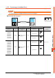
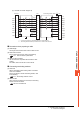
11.3.1 RS-232 cable
Connection diagram
Precautions when preparing a cable
(3) Cable length
The length of the RS-232 cable must be 15m or less.
(4) GOT side connector
For the GOT side connector, refer to the following.
1.4.1 GOT connector specifications
(5) GE PLC side connector
Use the connector compatible with the GE PLC side
module.
For details, refer to the GE PLC user's manual.
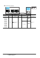
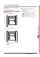
(1) RS-232 connection diagram 1)
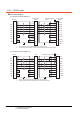
(2) RS-232 connection diagram 2)
*1 For details of the pin assignment, refer to the following
manual.
GE PLC user's Manual
Communication Modules
1
2
3
4
5
6
7
8
9
-
GOT side
1
2
3
4
7
5
8
20
CD
RD(RXD)
SD(TXD)
ER(DTR)
SG
DR(DSR)
RS(RTS)
CS(CTS)
NC
FG
SHILD
TD
RD
RTS
SG
CTS
DCD
DTR
PLC
1
2
3
4
5
6
7
8
9
-
GOT side
*
1
4
3
1
8
2
5
6
7
CD
RD(RXD)
SD(TXD)
ER(DTR)
SG
DR(DSR)
RS(RTS)
CS(CTS)
NC
FG
TXD
RXD
RTS
GND
CTS
DCD
DTR
5V