
Specifications


9. CONNECTION TO RKC TEMPERATURE CONTROLLER
9.5 Temperature Controller Side Setting
9 - 49
CONNECTION TO RKC TEMPERATURE CONTROLLER
9
HINTHINTHINT
The rotary switch (address setting switch) is also used
for the data interval extension time setting.
The setting method is the same as that of the module
address.
For the data interval extension time, refer to the
following.
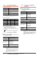
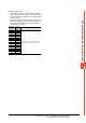
(4)Data interval extension time settings
(4) Data interval extension time settings
Set the data interval extension time as the following
procedure.
1. Turn the power of the module OFF.
2. Set the DIP switch 4 and 6 to ON and 5 to OFF.
3. Set the data interval extension time using the rotary
switch (address setting switch).
For the setting method, refer to the following.
(3)Module address settings
4. Turn the power of the module ON.
The FAIL/RUN lamp lights in green and the set time
becomes valid.
5. Turn the power of the module OFF again and set the
DIP switches and rotary switch to the original position.
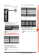
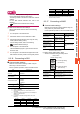
9.5.16 Connecting to SB1
Communication settings
Make the communication settings of SB1 using the
switch key on the front surface.
For the operation procedure, refer to the SB1 manual.
*1 Adjust the settings with GOT settings.
*2 Select 1: MODBUS.
*3 When the setting value is 0, communication is not
performed.
*4 The communication speed cannot be set to 2400bps or
4800bps on the GOT side.
Select 2 or 3.
*5 For details on the data bit configuration, refer to the
following.
*6 Set the maximum time from when the last character stop bit
is sent from the GOT side until the transmission cable
becomes ready to receive.
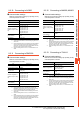
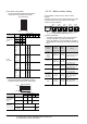
9.5.17 Connecting to B400
Communication settings
Make the communication settings of B400 using the
rotary switch key and the DIP switch.
For the operation procedure, refer to the B400 manual.
*1 When the setting value is 98 or 99, the communication
address is the same as for 97.
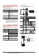
(1) Rotary switch setting (SW1, SW2)
Set the unit address using the rotary switch.
Item Setting range
Communication
protocol*2
0: RKC communication
1: MODBUS
Device address
*1*3
(Slave address)
0 to 99
Communication speed
*1*4
0: 2400bps
1: 4800bps
2: 9600bps
3: 19200bps
Data bit configuration
*1*5
0 to 5
Interval time
*6
0 to 250ms
Set value Data bit Parity bit Stop bit
08None1
18None2
28Even1
38Even2
48Odd1
58Odd2
Item Setting range Settings
Unit address setting
(CH1 to CH8)
0 to 99
*1
(1)Rotary switch setting
(SW1, SW2)
Communication speed
4800bps, 9600bps,
19200bps, 38400bps
(2)DIP switch setting
(SW3)
Data bit configuration 0 to 5
Communication
specification setting
RS-422A, RS-485
(3)DIP switch settings
(SW4)
Termination resistor
setting
Enable, Disable
Item Setting range
Unit address setting
(CH1 to CH4)
The communication address is the rotary
switch setting value + 1.
Unit address setting
(CH5 to CH8)
The communication address is the rotary
switch setting value + 2.
Set value Data bit Parity bit Stop bit
SW2: Upper digit setting
(Set value x10)
SW1: Lower digit setting
(Set value x1)
Rotary switch
(Address setting switch)