
Specifications

9. CONNECTION TO RKC TEMPERATURE CONTROLLER
9.3 Connection Diagram
9 - 35
CONNECTION TO RKC TEMPERATURE CONTROLLER
9
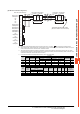
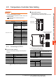
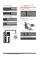
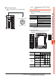
(6) RS-485 connection diagram 6)
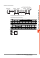
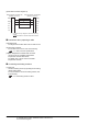
*1 Set the terminating resistor setting switch of the GOT main unit to "100 OHM". ■ Connecting terminating resistors
*2 When combining the module, because the communication line is connected between the modules with each other, wire only the
communication terminal on the both end of the combination module.
*3 Terminating resistor should be provided for a temperature controller which will be a terminal. When using X-TIO, turn ON the
terminating resistor selector in the terminal base. When combining the module, provide the terminating resistor to the end of the
combination module (the one that is far from the converter).
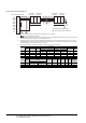
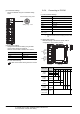
*4 For the terminal number of the temperature controller, refer to the following table.
Signal
name
Terminal No.
Z-TIO/
Z-CT
CB100/CB400
/CB500/CB900
CB700
FB100 FB400/FB90
RB100/RB400
/RB500/RB900
RB700
Communication 1 Communication 2 Communication 1 Communication 2
SG 5 13 7 13 16 25 25 13 25
T/R(A) 3 14 8 14 17 26 28 14 26
T/R(B) 4 15 9 15 18 27 29 15 27
GOT side
*
1
(terminal block)
*
4
*
4
*
4
*
4
SDA1(TXD1+)
SDB1(TXD1-)
NC
SG
NC
NC
SDA2(TXD2+)
SDB2(TXD2-)
RDA2(RXD2+)
RDA1(RXD1+)
RDB2(RXD2-)
RDB1(RXD1-)
NC
RSA(RTS+)
NC
RSB(RTS-)
NC
CSA(CTS+)
NC
CSB(CTS-)
6
8
1
2
3
4
5
7
9
10
11
12
13
14
15
16
17
18
19
20
T/R(B)
T/R(A)
SG
T/R(B)
T/R(A)
SG
Temperature
controller
Temperature
controller
Temperature
controller
Temperature
controller
Combination module
*
2
Combination module
*
2
T/R(B)
T/R(A)
SG
T/R(B)
T/R(A)
SG
Terminating resistor(120Ω 1/2W)
*
3
(More than 100Ω in case of CB series)
Signal
name
Terminal No.
PF900
PF901
AG500
HA400/401
HA900/901
MA900/
MA901
RMC500 X-TIO SA100 SA200 SB1
B400
(RS-485
specifications)
Communication 1 Communication 2
SG 25 13 25 44 13 17 1 10 1 3/6
T/R(A) 26 14 26 45 14 16 2 11 2 1/5
T/R(B) 27 15 27 46 15 15 3 12 3 2/4