
Specifications

9 - 30
9. CONNECTION TO RKC TEMPERATURE CONTROLLER
9.3 Connection Diagram
9.3 Connection Diagram
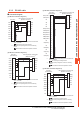
The following diagram shows the connection between the
GOT and the temperature controller.
9.3.1 RS-232 cable
Connection diagram
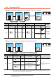
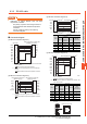
(4) RS-232 connection diagram 4)
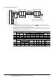
*1 For the terminal number of the temperature controller, refer
to the following table.
Precautions when preparing a cable
(5) Cable length
The length of the RS-232 cable must be 15m or less.
(6) GOT side connector
For the GOT side connector, refer to the following.
1.4.1 GOT connector specifications
(7) RKC temperature controller side connector
Use the connector compatible with the RKC
temperature controller side module.
For details, refer to user's manual of the RKC
temperature controller side.
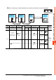
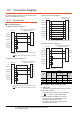
(1) RS-232 connection diagram 1)
*1 For details of the pin assignment, refer to the following
manual.
User's Manual of the RKC temperature controller
(2) RS-232 connection diagram 2)
*1 For details of the pin assignment, refer to the following
manual.
User's Manual of the RKC temperature controller
GOT side
CD
RD(RXD)
SD(TXD)
ER(DTR)
SG
DR(DSR)
RS(RTS)
CS(CTS)
-
NC
SD
RD
NC
SG
SG
1
2
3
4
5
6
7
8
9
1
2
4
5
3
6
RKC temperature controller side
(Modular connector)
*
1
GOT side
CD
RD(RXD)
SD(TXD)
ER(DTR)
SG
DR(DSR)
RS(RTS)
CS(CTS)
-
NC
SD
RD
NC
SG
CS
1
2
3
4
5
6
7
8
9
1
2
4
5
3
6
RKC temperature controller side
(Modular connector)
*
1
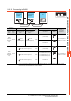
(3) RS-232 connection diagram 3)
*1 GT16: CD, GT15: CD, GT14: NC, GT12: NC, GT11: NC
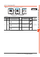
Signal
name
Terminal No.
FB400
FB900
PF900
PF901
HA400/401
HA900/901
MA900
MA901
Communication
1
Communication
2
SG 25 25 13 25 44
SD(TXD)2626142645
RD(RXD)2727152746
GOT side
Interface converter
(CD485/V) side
CD/NC
*
1
RD(RXD)
SD(TXD)
ER(DTR)
SG
DR(DSR)
RS(RTS)
CS(CTS)
N.C.
CD
RXD
TXD
DTR
GND
DSR
RTS
CTS
RI
1
2
3
4
5
6
7
8
9
1
2
3
4
5
6
7
8
9
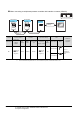
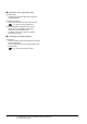
GOT side
CD
RD(RXD)
SD(TXD)
ER(DTR)
SG
DR(DSR)
RS(RTS)
CS(CTS)
-
SD(TXD)
RD(RXD)
SG
1
2
3
4
5
6
7
8
9
RKC temperature controller side
(Modular connector)
*
1