
Specifications

8. CONNECTION TO YOKOGAWA TEMPERATURE CONTROLLER
8.6 Device Range that Can Be Set
8 - 33
8
CONNECTION TO YOKOGAWA TEMPERATURE CONTROLLER
8.6 Device Range that Can Be Set
The device ranges of controller that can be used for GOT
are as follows.
Note that the device ranges in the following tables are the
maximum values that can be set in GT Designer3.
The device specifications of controllers may differ
depending on the models, even though belonging to the
same series.
Please make the setting according to the specifications of
the controller actually used.
When a non-existent device or a device number outside
the range is set, other objects with correct device settings
may not be monitored.
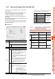
Setting item
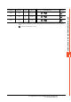
*1 The following shows the relation between station numbers of
the temperature controller and the GOT data register.
*2 When there is no setting for the CPU No. in the
communication settings on the temperature controller side,
set the CPU No. on the GOT side to (1) (default).
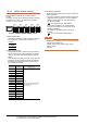
8.6.1 YOKOGAWA GREEN/UT100/
UT2000/UTAdvanced
*1 Only 16-bit (1-word) designation is allowed.
*2 This is available only for UP750 and UP550.
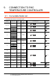
Item Description
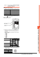
Device
Set the device name, device number, and bit number.
The bit number can be set only when specifying the bit of
word device.
CPU
No.
*2
Set the CPU No. (1, 2) of the device to be monitored.
When device B is selected, the CPU No. is fixed to 1.
Information
Displays the device setting range which are selected in [Device].
Network
Set the monitor target of the set device.
All
Select this item when writing data to all the
temperature controllers connected.
When bit specification of word device is performed,
data are written to the temperature controller of the
station No. set for [Host Address] of the
communication detail settings.
Monitoring and writing with bit specification of word
device are performed only for the station No. set for
[Host Address].
(When writing the data in numerical input, the data is
written to the connected temperature controller other
than the ones specified by the word device during
input, and the temperature controller set for [Host
Address] is monitored during other than input
(displaying).)
Statio
n No.
Select this item when monitoring the temperature
controller of the specified station No.
After selecting, set the station No. in the following
range.
1 to 99 : To monitor the temperature controller
of the specified station No.
100 to 115 : To specify the station No. of the
temperature controller to be monitored
by the value of GOT data register
(GD).
*1
Statio
n No.
GOT data register (GD) Setting range
100 GD10
1 to 99
(If setting a value
outside the range
above, a device
range error
occurs.)
101 GD11
::
114 GD24
115 GD25
Device name Setting range
Device No.
representation
Bit device
Internal relay (I) I0001 to I7072 Decimal
The bit specification of
the word device
*1
Setting range of each
word device
―
Word device
Data register (D)
*1
D0001 to D9000
Decimal
File register (B)
*1*2
B0001 to B1600
The word specification
of the bit device
Setting range of each bit
devices
―