
Specifications

8 - 22
8. CONNECTION TO YOKOGAWA TEMPERATURE CONTROLLER
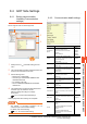
8.3 Connection Diagram
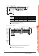
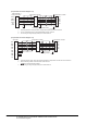
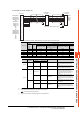
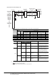
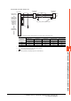
(16) RS-485 connection diagram 16)
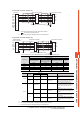
*1 Pin No. of temperature controller differs depending on the model. Refer to the following table.
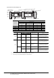
• For the product condition of UTAdvanced series, refer to the following table.
*2 Terminating resistor should be provided for a temperature controller which will be a terminal.
*3 Turn on the terminating switch on the RS232C/RS485 converter at the end.
*4 Connect FG grounding to the appropriate part of a cable shield line.
RDA(-)
RDB(+)
SDA(-)
SDB(+)
SG
3
4
1
2
5
6
RDA(-)
RDB(+)
SDA(-)
SDB(+)
SG
RDA(-)
RDB(+)
SDA(-)
SDB(+)
SG
GND
*
4
*
4
Temperature controller
*
1
Temperature controller
*
1
RS232C/RS485
interface converter
*
3
Terminating resistor (220Ω 1/4W)
*
2
Signal name
Model of temperature controller
UTAdvanced Series
UT32A/UP35A/UM33A
UT35A/
UT55A (product condition A)/
UP55A (product condition A)
UT55A (product condition B)/
UP55A (product condition B)
UT75A
Pin No. Pin No. Pin No. Pin No.
SDB (+) 301 407 501 1
SDA (-) 302 408 502 2
RDB (+) 304 410 504 4
RDA (-) 305 411 505 5
SG 303 409 503 3
Model
Product
condition
Suffix code
Optional suffix code Remark
Function Open network
UT55A
A
-
1
-
Product with the open network port of RS-
485 communication (4-wire type/2-wire
type)
B1 or 2
-
Without "/LP"
Product with two RS-485 communication
ports (4-wire type/2-wire type) and without
the power supply for 24VDC sensor
UP55A
A
Other than 3 1
-
Product without the additional contact
output points (DO) and with the open
network port of RS-485 communication (4-
wire type/2-wire type) (Standard code
model)
--
With "/CH3"
Product with the RS-485 communication
port (4-wire type/2-wire type) specified in
the E3 terminal area option (Detailed code
model)
B
2
--
Product with two RS-485 communication
ports (4-wire type/2-wire type) (Standard
code model)
--
With "/C4"
Product with the RS-485 communication
port (4-wire type/2-wire type) specified in
the E4 terminal area option (Detailed code
model)