
Specifications

8 - 20
8. CONNECTION TO YOKOGAWA TEMPERATURE CONTROLLER
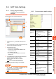
8.3 Connection Diagram
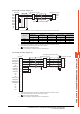
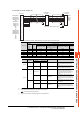
(12) RS-485 connection diagram 12)
*1 Terminating resistor should be provided for a temperature controller which will be a terminal.
*2 Turn on the terminating switch on the RS232C/RS485 converter at the end.
*3 Connect FG grounding to the appropriate part of a cable shield line.
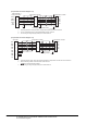
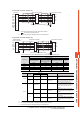
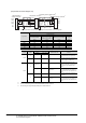
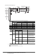
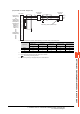
(13) RS-485 connection diagram 13)
*1 Terminating resistor having 100 Ω 1/2W should be provided for a temperature controller which will be a terminal.
*2 Set the terminating resistor of GOT side which will be a terminal.
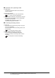
■ Connecting terminating resistors
*3 Connect FG grounding to the appropriate part of a cable shield line.
Temperature controller
TX-
TX+
RX+
RX-
SG
3
4
2
1
5
6
6
4
3
5
2
6
4
3
5
2
TX-
TX+
RX+
RX-
SG
RDA(-)
RDB(+)
SDB(+)
SDA(-)
SG
GND
Temperature controller
RS232C/RS485
interface converter
*
2
Terminating resistor(220Ω 1/4W)
*
1
*
3
*
3
Temperature controller
RX+
RX-
TX+
TX-
SG
1
6
2
7
5
3
4
8
9
-
3
5
4
6
2
3
5
4
6
2
RX+
RX-
TX+
TX-
SG
SDA
SDB
RDA
RDB
SG
RSA
CSA
RSB
CSB
FG
Temperature controllerGOT side
*
2
Terminating resistor
*
1
*
3
*
3