
Specifications

8 - 16
8. CONNECTION TO YOKOGAWA TEMPERATURE CONTROLLER
8.3 Connection Diagram
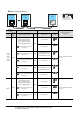
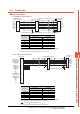
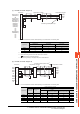
(5) RS-485 connection diagram 5)
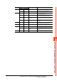
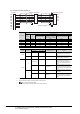
*1 Pin No. of temperature controller differs depending on the model.Refer to the following table.
*2 Terminating resistor should be provided for a temperature controller which will be a terminal.
*3 Turn on the terminating switch on the RS232C/RS485 converter at the end.
*4 Connect FG grounding to the appropriate part of a cable shield line.
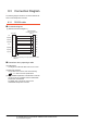
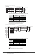
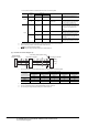
(6) RS-485 connection diagram 6)
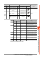
*1 Pin No. of temperature controller differs depending on the model.Refer to the following table.
*2 Terminating resistor should be provided for a temperature controller which will be a terminal.
*3 Set the terminating resistor of GOT side which will be a terminal.
■ Connecting terminating resistors
*4 Connect FG grounding to the appropriate part of a cable shield line.
Temperature controller
SDB(+)
SDA(-)
RDB(+)
RDA(-)
SG
4
3
5
6
SDB(+)
SDA(-)
RDB(+)
RDA(-)
SG
B(+)
A(-)
SG
GND
Temperature controller
RS23C/RS485
interface converter
*
3
Terminating resistor(220Ω 1/4W)
*
2
*
4
*
4
*
1
*
1
Signal name
Model of temperature controller
GREEN Series
UT/UP/UM
GREEN Series
US
Pin No. Pin No.
SDB (+) 23 21
SDA (-) 24 22
RDB (+) 25 23
RDA (-) 26 24
SG 27 25
Temperature controller
Temperature controller
SDB(+)
SDA(-)
RDB(+)
RDA(-)
SG
6
8
5
7
2
10
12
14
16
18
20
1
3
4
9
11
13
15
17
19
SDB(+)
SDA(-)
RDB(+)
RDA(-)
SG
SDA1(TXD1+)
SDB1(TXD1-)
SDA2(TXD2+)
SDB2(TXD2-)
SG
RDA1(RXD1+)
RDB1(RXD1-)
RSA(RTS+)
RSB(RTS-)
CSA(CTS+)
CSB(CTS-)
NC
NC
NC
RDA2(RXD2+)
RDB2(RXD2-)
NC
NC
NC
NC
GOT side
*
3
Terminating resistor(220Ω 1/4W)
*
2
*
4
*
4
*
1
*
1
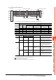
Signal name
Model of temperature controller
GREEN Series
UT/UP/UM
GREEN Series
US
Pin No. Pin No.
SDB (+) 23 21
SDA (-) 24 22
RDB (+) 25 23
RDA (-) 26 24
SG 27 25