
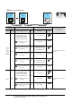
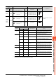
Specifications
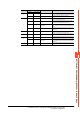

8 - 12
8. CONNECTION TO YOKOGAWA TEMPERATURE CONTROLLER
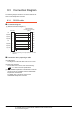
8.3 Connection Diagram
8.3 Connection Diagram
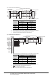
The following diagram shows the connection between the
GOT and the temperature controller.
8.3.1 RS-232 cable
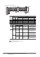
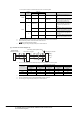
Connection diagram
Precautions when preparing a cable
(2) Cable length
The length of the RS-232 cable must be 15m or less.
(3) GOT side connector
For the GOT side connector, refer to the following.
1.4.1 GOT connector specifications
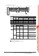
(4) YOKOGAWA temperature controller side connector
Use the connector compatible with the YOKOGAWA
temperature controller side.
For details, refer to the user's manual of the
YOKOGAWA temperature controller.
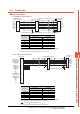
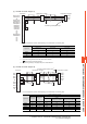
(1) RS-232 connection diagram 1)
*1 Connect FG grounding to the appropriate part of a cable
shield line.
GOT side
CD
RD(RXD)
SD(TXD)
ER(DTR)
SG
DR(DSR)
RS(RTS)
CS(CTS)
-
CD
RD
SD
ER
SG
DR
RS
CS
-
*
1
1
2
3
4
5
6
7
8
9
1
2
3
4
5
6
7
8
9
RS232C/RS485
Interface converter side
(ML2-□)