
Specifications

7 - 20
7. CONNECTION TO YOKOGAWA PLC
7.3 Ethernet Connection
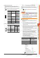
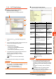
(2) Condition setting switch
Set the data format, write protection, line processing at
TCP timeout error or operation mode with the DIP
switch on the side of the base unit.
*1 Applicable to only F3LE01-5T.
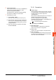
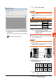
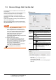
7.3.5 Connecting to Ethernet
Interface Module (F3LE12-0T)
Switch settings of Ethernet Interface Module
Set the switches accordingly.
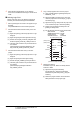
POINTPOINTPOINT
Switch setting
Set the switches before mounting the Ethernet
Interface Module on the base unit.
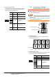
(1) IP address switch
Set the IP address with eight Hex rotary switches on
the side of the base unit.
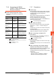
(2) Condition setting switch
Set the data format, write protection, or operation mode
with the DIP switch on the side of the base unit.
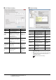
Switch
No.
Description Set value
1
Data
code
OFF (ASCII)
2
Write
protect
OFF (not protect)
3
Reserved
ON (not available),
OFF (always)
4
5
6
7
Line
processing
on TCP
timeout
*1
OFF (close the line)
8
Operation
mode
OFF (normal operation)
12 345678
OFF
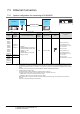
Switch
No.
Description Set value
1 Data code OFF (ASCII)
2 Write protect OFF (not protect)
3
Reserved
ON (not available),
OFF (always)
4
5
6
7
8
Operation
mode
OFF (normal operation)
F3LE12-0T
Condition setting switch
IP address switch
Right side view with the cover
0
1
2
3
4
5
6
7
8
9
A
B
C
D
E
F
0
1
2
3
4
5
6
7
8
9
A
B
C
D
E
F
0
1
2
3
4
5
6
7
8
9
A
B
C
D
E
F
0
1
2
3
4
5
6
7
8
9
A
B
C
D
E
F
0
1
2
3
4
5
6
7
8
9
A
B
C
D
E
F
0
1
2
3
4
5
6
7
8
9
A
B
C
D
E
F
0
1
2
3
4
5
6
7
8
9
A
B
C
D
E
F
0
1
2
3
4
5
6
7
8
9
A
B
C
D
E
F
Hexadecimal
Decimal
C0 A8 FA D2
192 168 250 210
12 345678
OFF