
Specifications

7. CONNECTION TO YOKOGAWA PLC
7.3 Ethernet Connection
7 - 19
7
CONNECTION TO YOKOGAWA PLC
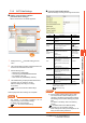
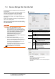
IP Filter Setting
To improve security, the GOT 2000 series supports the
IP Filter Setting.
For details on the IP Filter Setting, refer to the following
manual.
GT Designer3 (GOT2000) Help
7.3.3 PLC side setting
POINTPOINTPOINT
YOKOGAWA PLC
For details of YOKOGAWA PLCs, refer to the following
manuals.
YOKOGAWA PLC user's Manual
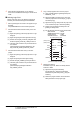
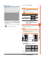
7.3.4 Connecting to Ethernet
Interface Module (F3LE01-5T,
F3LE11-0T)
Switch settings of Ethernet Interface Module
Set the switches accordingly.
POINTPOINTPOINT
Switch setting
Set the switches before mounting the Ethernet
Interface Module on the base unit.
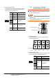
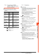
(1) IP address switch
Set the IP address with eight Hex rotary switches on
the side of the base unit
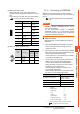
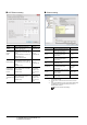
Model name Refer to
Ethernet interface module
F3LE01-5T
7.3.4
F3LE11-0T
F3LE12-0T 7.3.5
Built-in Ethernet interface
F3SP66
7.3.6F3SP67
F3SP71-4N
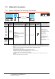
F3LE01-5T F3LE11-0T
Condition setting
switch
IP address switch
Right side view without the cover
0
1
2
3
4
5
6
7
8
9
A
B
C
D
E
F
0
1
2
3
4
5
6
7
8
9
A
B
C
D
E
F
0
1
2
3
4
5
6
7
8
9
A
B
C
D
E
F
0
1
2
3
4
5
6
7
8
9
A
B
C
D
E
F
0
1
2
3
4
5
6
7
8
9
A
B
C
D
E
F
0
1
2
3
4
5
6
7
8
9
A
B
C
D
E
F
0
1
2
3
4
5
6
7
8
9
A
B
C
D
E
F
0
1
2
3
4
5
6
7
8
9
A
B
C
D
E
F
Hexadecimal
Decimal
C0 A8 FA D2
192 168 250 210