
Specifications

7 - 18
7. CONNECTION TO YOKOGAWA PLC
7.3 Ethernet Connection
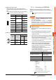
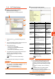
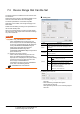
GOT Ethernet setting Ethernet setting
*1 Set the same IP address and communication format as
those of the PLC side.
*2 Set the port No. of the host link service used on the PLC
side.
*3 Each of [GOT Station] set in the communication detail setting
and [Station] set in the Ethernet setting must be set to
different station numbers.
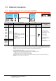
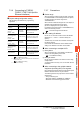
■ Communication detail settings
Item Description Range
GOT IP
Address
Set the IP address of the GOT.
(Default: 192.168.0.18)
0.0.0.0 to
255.255.255.255
Subnet
Mask
Set the subnet mask for the sub
network.(Only for connection via
router)
If the sub network is not used, the
default value is set.
(Default: 255.255.255.0)
0.0.0.0 to
255.255.255.255
Default Gateway
Set the router address of the
default gateway where the GOT is
connected.(Only for connection via
router)
(Default: 0.0.0.0)
0.0.0.0 to
255.255.255.255
Periphral S/W
Communication
Port No.
Set the GOT port No. for the S/W
communication.
(Default: 5015)
1024 to 5010,
5014 to 65534
(Except for 5011,
5012, 5013 and
49153)
Transparent Port
No.
Set the GOT port No. for the
transparent function.
(Default: 5014)
1024 to 5010,
5014 to 65534
(Except for 5011,
5012, 5013 and
49153)
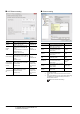
Item Description Set value
Host
The host is displayed.(The host is
indicated with an asterisk (*).)
―
Net No.
Set the network No. of the
connected Ethernet module.
(Default: blank)
1 to 239
Station
*3
Set the station No. of the
connected Ethernet module.
(Default: blank)
1 to 64
Type YOKOGAWA (fixed)
YOKOGAWA
(fixed)
IP address
*1
Set the IP address of the
connected Ethernet module.
(Default: blank)
PLC side IP
address
Port No.
*2
Set the port No. of the connected
Ethernet module.
(Default: 12289)
12289, 12291
Communication
format
*1
Select a communication protocol.
(Default: UDP)
UDP, TCP