
Specifications

7 - 12
7. CONNECTION TO YOKOGAWA PLC
7.2 Serial Connection
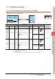
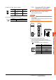
(2) Data format switch (SW2)
Set the character length, parity, stop bit and checksum
consistent with the corresponding settings on the GOT
side.
For the settings on the GOT side, refer to the following.
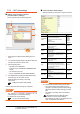
7.2.5 ■ Communication detail settings
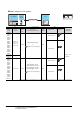
(3) Module function switch (SW3)
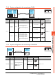
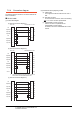
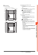
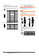
7.2.10 Connecting PC link module
(LC01-0N, LC02-0N)
Switch setting on the PC link module
Set the switches accordingly.
POINTPOINTPOINT
Switch setting
Set the switches before mounting the Ethernet
Interface
Module on the base unit.
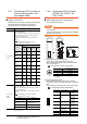
(1) Transmission speed setting switch
Set the same transmission speed of the GOT.
For the transmission speed setting on the GOT side,
refer to the following.
7.2.5 ■ Communication detail settings
*1 Only transmission speeds available on the GOT side are
shown.
Switch No. Description Settings
1 Character length
ON (8bits),
OFF (7bits)
2
Parity
ON (done),
OFF (none)
3
ON (even),
OFF (odd)
4 Stop bit
ON (2bits),
OFF (1bit)
5 Checksum
ON (done),
OFF (none)
6
End character
specification
OFF (none)
7 Protect function OFF (disabled)
8 Security function OFF (disabled)
Switch No. Description Settings
1 to 6
User setting
inhibited
OFF
7
Modem
compatibility
OFF (not
compatible)
8 External modem OFF (none)
1
2
3
4
5
6
7
8
O
F
F
1
2
3
4
5
6
7
8
O
F
F
Setting
*1
Transmission speed
4 4800bps
5 9600bps
6 19200bps
Front
LC01-0N
Rear
1
2
3
4
5
6
7
8
OFFON
(1)
(3)
(2)
Front
LC02-0N
Rear
1
2
3
4
5
6
7
8
OFFON
(1)
(2)
STATION NO.
0
1
2
3
4
5
6
7
8
9