
Specifications

7. CONNECTION TO YOKOGAWA PLC
7.2 Serial Connection
7 - 11
7
CONNECTION TO YOKOGAWA PLC
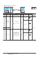
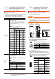
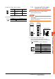
(3) Station No. switch (F3LC11-2N only)
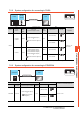
(4) Terminator switch (F3LC11-2N only)
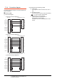
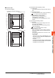
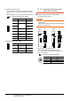
7.2.9 Connecting PC link module
(F3LC11-1F, F3LC12-1F)
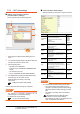
Switch setting on the PC link module
Set the switches accordingly.
POINTPOINTPOINT
Switch setting
Set the switches before mounting the Ethernet
Interface
Module on the base unit.
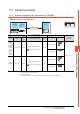
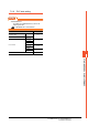
(1) Transmission speed switch (SW1)
Set the same transmission speed of the GOT.
For the transmission speed setting on the GOT side,
refer to the following.
7.2.5 ■ Communication detail settings
*1 Only transmission speeds available on the GOT side are
shown.
Rotary
switch
Description Settings
1)
Station No.
(10's digit)
0
2)
Station No.
(1's digit)
1
Settings Description
4-WIRE Resistor connected (4-wire type)
0
1
2
3
4
5
6
7
8
9
0
1
2
3
4
5
6
7
8
9
TERMINATOR
2-
OFF
4-
WIRE
Setting
*1
Transmission speed
4 4800bps
5 9600bps
7 19200bps
9 38400bps
A 57600bps
C 115200bps
A
(1)
Side view indicated by A
(2)
(3)
A
0
1
2
3
4
5
6
7
8
9
A
B
C
D
1
2
3
4
5
6
7
8
O
F
F
F3LC11-1F F3LC12-1F
2
1
SW2
SW1
1
2
3
4
5
6
7
8
O
F
F
SW3
With right side cover
removed
0
1
2
3
4
5
6
7
8
9
A
B
C
D
E
F