
Specifications

7 - 10
7. CONNECTION TO YOKOGAWA PLC
7.2 Serial Connection
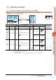
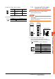
7.2.7 Connecting to CPU port/D-sub
9-pin conversion cable, SIO
port adapter cable
Setting of PLC CPU
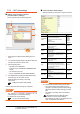
Make the PLC CPU settings, displaying [Configuration]
[Communication Settings] with the program
development tool or the ladder-programming tool.
*1 The communication mode that can be selected differs
according to the CPU.
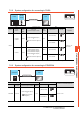
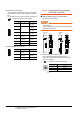
7.2.8 Connecting PC link module
(F3LC01-1N, F3LC11-1N,
F3LC11-2N)
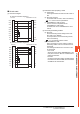
Switch setting on the PC link module
Set the switches accordingly.
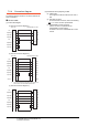
POINTPOINTPOINT
Switch setting
Set the switches before mounting the Ethernet
Interface
Module on the base unit.
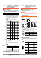
(1) Transmission speed setting switch
Set the same transmission speed of the GOT.
For the transmission speed setting on the GOT side,
refer to the following.
7.2.5 ■ Communication detail settings
*1Only transmission speeds available on the GOT side
are shown.
(2) Data format setting switch
Set the data length, parity, stop bit and checksum
consistent with the corresponding settings on the GOT
side.
For the settings on the GOT side, refer to the following.
7.2.5 ■ Communication detail settings
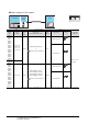
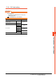
Item Set value
Communication
mode
*1
Set the communication mode of the CPU (transmission
speed and data format).
Set the transmission speed and data format according to
settings of the transmission speed, data length, parity
and stop bit on the GOT side.
For details on these GOT side settings, refer to the
following.
7.2.5Setting communication interface
(Communication settings)
Item
Transmission speed and data format
Transmis
sion
speed
Data bit Parity
Stop
bit
Communication
mode 0
9600
bps
8bits Even 1bit
Communication
mode 1
9600
bps
8bits None 1bit
Communication
mode 2
19200
bps
8bits Even 1bit
Communication
mode 3
19200
bps
8bits None 1bit
Communication
mode 4
38400
bps
8bits Even 1bit
Communication
mode 5
38400
bps
8bits None 1bit
Communication
mode 6
57600
bps
8bits Even 1bit
Communication
mode 7
57600
bps
8bits None 1bit
Communication
mode 8
115200
bps
8bits Even 1bit
Communication
mode 9
115200
bps
8bits None 1bit
CPU PC link
function
settings
Set the following when using the CPU programming port
as the PC link function.
Make the checksum setting according to the sum check
setting on the GOT side.
For the sum check setting on the GOT side, refer to the
following.
7.2.5 ■ Setting communication interface
(Communication settings)
Item Set value
Use of PC link function Mark. (Use enabled)
Checksum
Mark. (ON)
Do not mark. (OFF)
End character Do not mark. (OFF)
Protect function Do not mark. (OFF)
Setting
*1
Transmission speed
4 4800bps
5 9600bps
6 19200bps
Switch No. Description Settings
1 Data bit
ON (8bits),
OFF (7bits)
2
Parity
ON (done),
OFF (none)
3
ON (even),
OFF (odd)
4 Stop bit
ON (2bits),
OFF (1bit)
5 Checksum
ON (done),
OFF (none)
6
End character
specification
OFF (none)
7 Protect function OFF (disabled)
8—OFF
STATION
NO.
TERMINATOR
2-
SD A
OFF
4-
WIRE
0
1
2
3
4
5
6
7
0
1
2
3
4
5
6
7
SD B
RD A
SD B
SG
SHIELD
(3)
A
(1)
Side view indicated by A
(2)
(4)
A
0
1
2
3
4
5
6
7
1
2
3
4
5
6
7
8
O
F
F
F3LC01-1N,F3LC11-1N F3LC11-2N
With right side cover
removed
0
1
2
3
4
5
6
7
8
9
1
2
3
4
5
6
7
8
O
F
F