
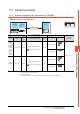
Specifications

7 - 6
7. CONNECTION TO YOKOGAWA PLC
7.2 Serial Connection
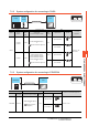
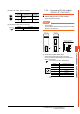
7.2.4 Connection diagram
The following diagram shows the connection between the
GOT and the PLC.
RS-232 cable
(1) Connection diagram
(2) Precautions when preparing a cable
(a) Cable length
The length of the RS-232 cable must be 15m or
less.
(b) GOT side connector
For the GOT side connector, refer to the following.
1.4.1 GOT connector specifications
(c) YOKOGAWA PLC side connector
Use the connector compatible with the
YOKOGAWA PLC side module.
For details, refer to the YOKOGAWA PLC user's
manual.
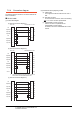
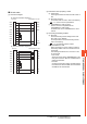
(a) RS-232 connection diagram 1)
(b) RS-232 connection diagram 2)
*1 Connect the shield to the housing of the connectors on
both the GOT and YOKOGAWA product sides.
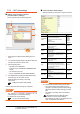
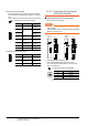
(c) RS-232 connection diagram 3)
GOT side
1
2
3
4
5
6
7
8
9
YOKOGAWA PLC side
-
3
2
-
5
SHIELD
CD
RD(RXD)
SD(TXD)
ER(DTR)
SG
DR(DSR)
RS(RTS)
CS(CTS)
-
-
SD
RD
-
SG
-
GOT side
1
2
3
4
5
6
7
8
9
-
YOKOGAWA PLC side
1
3
2
6
5
4
7
8
9
-
CD
RD(RXD)
SD(TXD)
ER(DTR)
SG
DR(DSR)
RS(RTS)
CS(CTS)
-
Shell
*
1
-
SD
RD
DR
SG
ER
RS
CS
-
Shell
*
1
GOT side
1
2
3
4
5
6
7
8
9
YOKOGAWA PLC side
1
2
3
6
7
20
4
5
CD
RD(RXD)
SD(TXD)
ER(DTR)
SG
DR(DSR)
RS(RTS)
CS(CTS)
-
FG
SD
RD
DR
SG
ER
RS
CS