
Specifications

6 - 12
6. CONNECTION TO YASKAWA PLC
6.2 Serial Connection
(2) Precautions when preparing a cable
(a) Cable length
The maximum length of the RS-232 cable differs
according to the specifications of the YASKAWA
PLC side.
For details, refer to the YASKAWA PLC user's
manual.
(b) GOT side connector
For the GOT side connector, refer to the following.
1.4.1 GOT connector specifications
(c) YASKAWA PLC side connector
Use the connector compatible with the YASKAWA
PLC side module.
For details, refer to the YASKAWA PLC user's
manual.
RS-422 cable
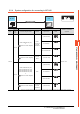
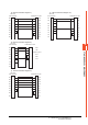
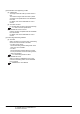
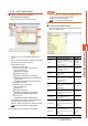
(1) Connection diagram
(a) RS-422 connection diagram 1)
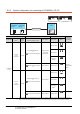
(b) RS-422 connection diagram 2)
*1 The terminating resistor (120 ) is valid by connecting pin
1 with pin 4 and pin 5 with pin 6 of the YASKAWA PLC
side.
GOT side
RDA
RDB
SDA
SDB
RSA
RSB
CSA
CSB
SG
FG
2
9
3
6
1
4
8
7
2
7
1
6
3
8
4
9
5
-
SDA
SDB
RDA
RDB
PGND
Receiving side
termination
Sending side
termination
SG
YASKAWA PLC side
GOT side
RDA
RDB
SDA
SDB
RSA
RSB
CSA
CSB
SG
FG
7
5
2
1
3
6
4
8
2
7
1
6
3
8
4
9
5
-
TX+
TX-
RX+
RX-
-
TXR+
RXR+
SG
YASKAWA PLC side
*
1
*
1
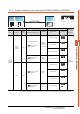
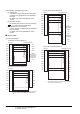
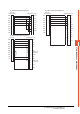
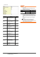
(c) RS-422 connection diagram 3)
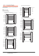
(d) RS-422 connection diagram 4)
*1 Connect RXR with RX(-) and TXR with TX(-) of 217IF01,
and insert the terminating resistor.
GOT side
RDA
RDB
SDA
SDB
RSA
RSB
CSA
CSB
SG
FG
1
2
3
4
5
6
7
14
9
10
11
12
13
8
2
7
1
6
3
8
4
9
5
-
YASKAWA PLC side
TX+
TX-
RX+
RX-
-
RX-
Receiving side
termination
GND
TX-
RX+
Sending side
termination
-
VCC
TX+
GOT side
RDA
RDB
SDA
SDB
RSA
RSB
CSA
CSB
SG
FG
1
2
3
4
5
6
7
8
14
10
11
12
13
9
2
7
1
6
3
8
4
9
5
-
YASKAWA PLC side
TX+
TX-
RX+
RX-
-
RX-
RXR
TX+
GND
RX+
TXR
-
VCC
TX-
*
1
*
1