
Specifications

5 - 18
5. CONNECTION TO FUJI TEMPERATURE CONTROLLER
5.5 Temperature Controller Side Setting
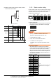
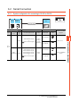
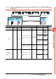
(2) Settings of data length, parity bit, stop bit, master/
slave device and echoback
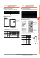
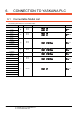
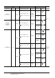
5.5.8 Station number setting
Set each station number so that no station number overlaps.
The station number can be set without regard to the cable
connection order. There is no problem even if station
numbers are not consecutive.
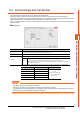
(1) Direct specification
When setting the device, specify the station number of the
temperature controller of which data is to be changed.
POINTPOINTPOINT
Specifying a station No. between 200 and 215
(Example of specifying the station No. 215)
1. Set the station No. to "200".
2. Input "215" to the internal device GD10.
3. The station No. 215 is specified.
For details, refer to (2) Indirect specification shown
below.
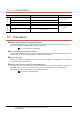
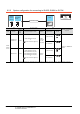
(2) Indirect specification
When setting the device, indirectly specify the station
number of the inverter of which data is to be changed using
the 16-bit GOT internal data register (GD10 to GD25).
When specifying the station No. from 200 to 215 on GT
Designer3, the value of GD10 to GD25 compatible to
the station No. specification will be the station No. of
the temperature controller.
Setting item Set value
Switch No.
4 5 6 7 8 9 0
Stop bit 1bit ON
Parity bit
Even OFF OFF
Odd ON OFF
None OFF ON
Communicati
on Type
RS-232C
RS-485
OFF OFF
Echo back Without OFF
ON
SW
Set these switches.
Specification range
1 to 199
216 to 255
Specification
station NO.
Compatible
device
Setting range
200 GD10
1 to 255
For the setting other than the above, error
(dedicated device is out of range) will
occur.
201 GD11
202 GD12
203 GD13
204 GD14
205 GD15
206 GD16
207 GD17
208 GD18
209 GD19
210 GD20
211 GD21
212 GD22
213 GD23
214 GD24
215 GD25
GOT
Station
No.3
Station
No.7
Station
No.1
Station
No.15
Station
No.6
Examples of station number setting