
Specifications

5. CONNECTION TO FUJI TEMPERATURE CONTROLLER
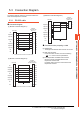
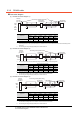
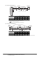
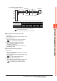
5.3 Connection Diagram
5 - 9
5
CONNECTION TO FUJI TEMPERATURE CONTROLLER
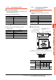
(4) RS-485 connection diagram 4)
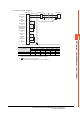
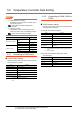
*1 Pin No. of temperature controller differs depending on the model. Refer to the following table.
*2 Terminating resistor should be provided for a temperature controller which will be a terminal.
*3 Set the terminating resistor of GOT side which will be a terminal.
■ Connecting terminating resistors
*4 Connect FG grounding to the appropriate part of a cable shield line.
GOT side
*
3
*
4
*
4
SDA1(TXD1+)
SDB1(TXD1-)
NC
SG
SDA2(TXD2+)
NC
SDB2(TXD2-)
NC
RDA2(RXD2+)
RDA1(RXD1+)
RDB2(RXD2-)
RDB1(RXD1-)
NC
RSA(RTS+)
NC
RSB(RTS-)
NC
CSA(CTS+)
NC
CSB(CTS-)
6
8
1
2
5
3
7
4
9
10
11
12
13
14
15
16
17
18
19
20
+
*
1
-
*
1
+
*
1
-
*
1
Temperature
controller side
Temperature
controller side
Terminating resistor(100Ω 1/2W)
*
2
Signal name
Model of temperature controller
PXR3 PXR4 PXR5/9 PXG4 PXG5/9 PXH9
Pin No. Pin No. Pin No. Pin No. Pin No. Pin No.
+15717114
-14828216