
Specifications

5. CONNECTION TO FUJI TEMPERATURE CONTROLLER
5.3 Connection Diagram
5 - 7
5
CONNECTION TO FUJI TEMPERATURE CONTROLLER
5.3 Connection Diagram
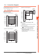
The following diagram shows the connection between the
GOT and the temperature controller.
5.3.1 RS-232 cable
Connection diagram
Precautions when preparing a cable
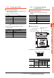
(4) Cable length
The length of the RS-232 cable must be 15m or less.
(5) GOT side connector
For the GOT side connector, refer to the following.
1.4.1 GOT connector specifications
(6) FUJI temperature controller side connector
Use the connector compatible with the FUJI
temperature controller side.
For details, refer to the user's manual of the FUJI
temperature controller.
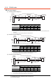
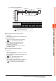
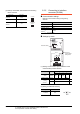
(1) RS-232 connection diagram 1)
*1 Use the interface converter in the DCE mode.
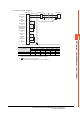
(2) RS-232 connection diagram 2)
*1 Use the interface converter in the DCE mode.
GOT side
CD
RD(RXD)
SD(TXD)
ER(DTR)
SG
DR(DSR)
RS(RTS)
CS(CTS)
NC
FG
CD
RXD
TXD
DTR
SG
DSR
RTS
CTS
NC
1
2
3
4
5
6
7
8
9
-
1
2
3
4
5
6
7
8
9
Interface
converter side
(RC-77
*
1
)
GOT side
NC
RD(RXD)
SD(TXD)
ER(DTR)
SG
DR(DSR)
RS(RTS)
CS(CTS)
NC
FG
FG
RXD
TXD
DTR
SG
DSR
RTS
CTS
NC
NC
1
2
3
4
5
6
7
8
9
-
1
3
2
20
7
6
4
5
9
Other than
above
Interface
converter side
(SI-30A
*
1
,KS-485)
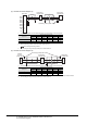
(3) RS-232 connection diagram 3)
GOT side
-
RD(RXD)
SD(TXD)
ER(DTR)
SG
DR(DSR)
RS(RTS)
CS(CTS)
NC
FG
SG
RD
SD
1
2
3
4
5
6
7
8
9
-
3
6
5
Interface
converter side
(K3SC-10)