
Specifications


4 - 28
4. CONNECTION TO FUJI PLC
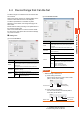
4.4 Device Range that Can Be Set
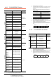
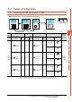
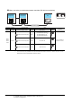
4.4.1 FUJI MICREX-F Series
*1 Only reading is possible.
*2 Only 32-bit (2-word) designation is allowed.
*3 Decimal points are not displayed.
*4 To read/write data from/to a user file, set SI data for the data
format of the PLC CPU and 16 bits for data length on GT
Designer3.
With any setting other than the above, the PLC does not
operate normally.
*5 As bit specification of a word device is performed after the
GOT reads the value, do not change the value in the
sequence program during this period.
*6 When it is used with bit specification (bit specification of word
device), the offset function cannot be used.
*7 When bit specification (bit specification of word device) is
performed, the uppermost bit is b0 and the lowermost bit is
b15.
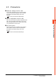
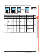
4.4.2 FUJI MICREX-SX Series
*1 As bit specification of a word device is performed after the
GOT reads the value, do not change the value in the
sequence program during this period.
*2 When it is used with bit specification (bit specification of word
device), the offset function cannot be used.
*3 When bit specification (bit specification of word device) is
performed, the uppermost bit is b0 and the lowermost bit is
b15.
Device name Setting range
Device No.
representation
Bit device
I/O relay (B) B0000 to B511F
Decimal +
Hexadecimal
Auxiliary relay (M) M0000 to M511F
Keep relay (K) K0000 to K063F
Special relay (F)
*1
F0000 to F125F
Annunciator relay
(A)
A0000 to A045F
Differential relay (D) D0000 to D063F
Link memory (L) L0000 to L511F
Timer output
(0.01s) (T)
T000 to T511
DecimalTimer output
(0.1s) (T)
T512 to T999
Counter output (C) C000 to C511
Word device bit
*5
Specified bit of the following
word devices
Direct access,
user file
―
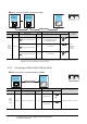
Word device
I/O relay (WB) WB000 to WB511
Decimal
Auxiliary relay (WM) WM000 to WM511
Keep relay (WK) WK000 to WK063
Special relay (WF)
*1
WF000 to WF125
Annunciator relay
(WA)
WA000 to WA045
Word device
Differential relay
(WD)
WD000 to WD063
Decimal
Link memory (WL) WL000 to WL511
Direct access
(W24)
*6*7
W24:0000 to W24:0255
User file (W30)
*4*6*7
User file (W31)
*4*6*7
:
User file
(W108)
*4*6*7
User file
(W109)
*4*6*7
W30:0000 to W30:4095
W31:0000 to W31:4095
:
W108:0000 to W108:4095
W109:0000 to W109:4095
Decimal
Data memory
(BD)
*2
BD0 to BD4095
Timer set value
(0.01s) (TS)
*2*3
TS0 to TS511
Timer current value
(0.01s) (TR)
*2*3
TR0 to TR511
Timer current value
(0.1s) (W9)
*2*3
W9:0000 to W9:0487
Counter set value
(CS)
*2*3
CS0 to CS511
Counter current
value (CR)
*2*3
CR0 to CR511
Data format of the PLC
CPU
GT Designer3 setting
SI (Binary 16-bit length) Device data bit: 16 bits
DI (Binary 32-bit length) Cannot be used
BD (8-digit BCD) Cannot be used
Higher Lower
b0 b1 .......... b14 b15
Device name Setting range
Device No.
representation
Bit device
Word device bit
*1
Specified bit of the following
word devices
Direct access,
User file
―
Word device
Non-retain
memory(M)
*2*3
M0 to M2097151
Decimal
Retain memory
(L)
*2*3
L0 to L2097151
System memory
(SM)
*2*3
SM0 to SM511
Higher Lower
b0 b1 .......... b14 b15