
Specifications

4. CONNECTION TO FUJI PLC
4.2 Serial connection
4 - 21
4
CONNECTION TO FUJI PLC
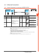
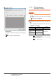
(a) Setting of the MODE
Make the MODE settings using the MODE switch.
(b) Setting of the station No.
Make the station No. using RS-485 station No.
switches.
(c) Connecting terminating resistors
Turn ON/OFF the terminating resistor using RS-
485 terminating resistor ON/OFF switch.
(d) Setting of Stop bit, Data bit, Parity bit, Initializing
method
Make the settings using the character configuration
switches.
(e) Transmission speed settings
Make the settings using the baudrate setting
switches.
Connecting to NP1L-RS1, NP1L-RS2,
NP1L-RS3, NP1L-RS4, NP1L-RS5
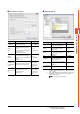
(1) Communication settings
Make the communication settings using setting
switches.
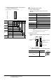
*1 Set the MODE switch so that the communication port of the
general communication module to be connected to the GOT
operates as a loader.
*2 The switch is not used for connection with the GOT.
*3 Turn ON the terminating switch of the general
communication module which will be a terminal.
MODE Switch position
Command-setting-type start-stop
synchronization, nonsequence
format
RS-232C 1:1
1
Command-setting-type start-stop
synchronization, nonsequence
format
RS-232C 1:1,
and RS-485 1:N
2
Command-setting-type start-stop
synchronization, nonsequence
format
RS-485 1:N
3
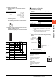
Station No.
0 to 99
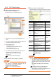
Setting item Set value
Switch No.
1 2 3 4 5 6 7 8
disable
OFF OFF OFF
Stop bit
1bit ON
2bits
OFF
Data bit
7bits ON
8bits
OFF
Parity bit
Even ON
Odd
OFF
Done ON
None
OFF
Initializing
method
By switch ON
ON
8
7
6
5
4
3
2
1
ON
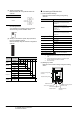
Setting item Set value
Switch No.
1 2 3 4 5 6 7 8
Transmission
speed
9600bps OFF OFF OFF OFF OFF ON OFF OFF
19200bps OFF OFF OFF OFF OFF OFF ON OFF
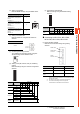
Switch Item Set value
MODE switch MODE
1 to 3
*1
RS485 station No.
switch
Station No.
*2
RS485 terminator
switch
Terminator
*3
8
7
6
5
4
3
2
1
ON
MODE switch
RS485 station
No. switch
RS485
terminator switch