
Instruction manual


8. HOST COMMUNICATION
IMSRM52-E5
65
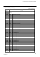
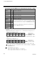
List of remote register (4 stations occupied, Temperature control 8 channels)
If “1: 8 Channels” is selected by the number of Control & Communication Link occupying channels
(ZC), the content of the remote register becomes as follows.
For details on the remote register when “0: 16 channels” is not changed prior to factor shipment, see
6.3 Remote Registers (P. 43).
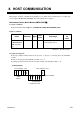
“n” and “m” in the table are the addresses assigned to the master station by the station No.
setting. They can be calculated by the following equations:
n = (Station No. − 1) × 4 m = (Station No. − 1) × 4
As the calculation results are expressed in decimal digits, they are converted to hexadecimal
digits before substituted for “n” and “m” in the table.
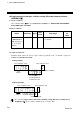
Example: If the station No. of the H-LNK-A module is “1” or “5”
For station No. 1: Remote register RWrn to RWrn+F → RWr0 to RWrF
RWwm to RWwm+F → RWw0 to RWwF
For station No. 5: Remote register RWrn to RWrn+F → RWr10 to RWr1F
RWwm to RWwm+F → RWw10 to RWw1F
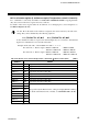
Direction: Remote device station (Temperature control unit) → Master station (PLC) [RWr]
Address Details
RWrn
CH1 Temperature measured value (PV)
RWrn+1
CH2 Temperature measured value (PV)
RWrn+2
CH3 Temperature measured value (PV)
RWrn+3
CH4 Temperature measured value (PV)
RWrn+4
CH5 Temperature measured value (PV)
RWrn+5
CH6 Temperature measured value (PV)
RWrn+6
CH7 Temperature measured value (PV)
RWrn+7
CH8 Temperature measured value (PV)
RWrn+8
CH1
RWrn+9
CH2
RWrn+A
CH3 Data specified by the Extension No. setting for display [RYn0 to RYn5] *
RWrn+B
CH4 For details of the Extension No. and data, see 6.4 Extension No. (P. 45).
RWrn+C
CH5
RWrn+D
CH6
RWrn+E
CH7
RWrn+F
CH8
For details, see page 66.