
Instruction manual

6. REMOTE INPUT/OUTPUT AND REMOTE REGISTERS
IMSRM52-E5
44
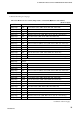
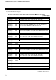
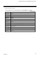
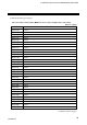
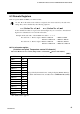
Direction: Master station (PLC) → Remote device station (Temperature control unit)
[RWw]
Address Details
RWwm
CH1
RWwm+1
CH2
RWwm+2
CH3
RWwm+3
CH4
RWwm+4
CH5
RWwm+5
CH6
RWwm+6
CH7 Data specified by the Extension No. setting for setting [RYn6 to RYnB] *
RWwm+7
CH8 For details of the Extension No. and data, refer to 6.4 Extension No. (P. 45).
RWwm+8
CH9
RWwm+9
CH10
RWwm+A
CH11
RWwm+B
CH12
RWwm+C
CH13
RWwm+D
CH14
RWwm+E
CH15
RWwm+F
CH16
* Data on the Extension No. specified by the remote output [RYn0 to RYn5 or RYn6 to RYnB] is
processed.
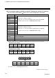
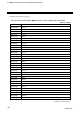
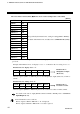
Example: When Extension No. for display is set to “1” or Extension No. for setting is set to “9.”
Extension No. for display: Set to “1”
RYn5 RYn4 RYn3 RYn2 RYn1 RYn0
OFF OFF OFF OFF OFF ON
Remote registers [RWrn to RWrn+F] become the Manipulated output (Heat-side) of CH1 to
CH16.
Extension No. for setting: Set to “9”
RYnB RYnA RYn9 RYn8 RYn7 RYn6
OFF OFF ON OFF OFF ON
Remote registers [RWwm to RWwm+F] become the 1st alarm set values of CH1 to CH16.
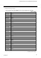
For details of the remote output [RYn0 to RYn5 or RYn6 to RYnB], refer to 6.2 Remote
Input/Output (P. 33).
Unused channels become as follows.
Remote registers, RWrn to RWrn+F → “0” is displayed.
Remote registers, RWwm to RWwm+F → Set data is ignored.
Extension No. 1:
Manipulated output
(Heat-side)
Extension No. 9:
1st alarm set value