SR Mini HG SYSTEM Power Supply/CPU Module Link Module [Control & Communication Link] H-PCP-G H-LNK-A Instruction Manual ® RKC INSTRUMENT INC.
z The MELSEC and Control & Communication Link system are products manufactured by Mitsubishi Electric Co., Ltd. z Company names and product names used in this manual are the trademarks or registered trademarks of the respective companies. All Rights Reserved, Copyright © 1998, RKC INSTRUMENT INC.
Thank you for purchasing this RKC product. In order to achieve maximum performance and ensure proper operation of your new instrument, carefully read all the instructions in this manual. Please place the manual in a convenient location for easy reference. SYMBOLS WARNING : This mark indicates precautions that must be taken if there is danger of electric shock, fire, etc., which could result in loss of life or injury.
CAUTION z This product is intended for use with industrial machines, test and measuring equipment. (It is not designed for use with medical equipment and nuclear energy.) z This is a Class A instrument. In a domestic environment, this instrument may cause radio interference, in which case the user may be required to take additional measures. z This instrument is protected from electric shock by reinforced insulation.
CONTENTS Page 1. OUTLINE ............................................................................... 1 1.1 Product Outline ................................................................................................ 1 1.2 Handling Procedure ......................................................................................... 2 1.3 Checking the Products .................................................................................... 3 1.4 Confirmation of the Model Code ......................
Page 5.4 When the Power is Turned on for the First Time ........................................... 31 5.5 Control Unit Operation When the PLC is Abnormal ....................................... 31 6. REMOTE INPUT/OUTPUT AND REMOTE REGISTERS .. 32 6.1 Communication Between Master Station and Remote Device Station .......... 32 6.2 Remote Input/Output ..................................................................................... 33 6.3 Remote Registers ................................................
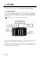
1. OUTLINE This manual should be used in conjunction with Hardware Quick Manual (IMS01V01-E). 1.1 Product Outline The control unit for the SR Mini HG SYSTEM can easily configure a temperature control/monitoring system on Control & Communication Link by connecting it with Control & Communication Link. In addition, the control unit for the SR Mini HG SYSTEM correspond to Control & Communication Link Ver. 1.10.
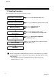
1. OUTLINE 1.2 Handling Procedure Proceed with the work according to the following procedure. Confirmation of the products Confirmation of the model code Mounting and Wiring Station No. and transmission speed settings Programming Turn on the power Refer to 1.3 Checking the Products (P. 3). Refer to 1.4 Confirmation of the Model Code (P. 4). Refer to 3. MOUNTING (P. 15). Refer to 4. WIRING (P. 23). Refer to 5.1 Station No. Setting (P. 28). Refer to 5.2 Transmission Speed Setting (P. 29).
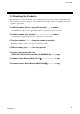
1. OUTLINE 1.3 Checking the Products When unpacking your new instrument, please confirm that the following products are included. If any of the products are missing, damaged, or if your manual is incomplete, please contact RKC sales office or agent for replacement. H-PCP-G module (Power supply/CPU module).......... 1 module One H-PCP-H module (power supply/CPU module) is required for each control unit. H-LNK-A module (Link module) ..................................
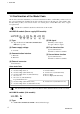
1. OUTLINE 1.4 Confirmation of the Model Code The model code for the instrument you received is listed below. Please confirm that you have received the correct instrument by checking the model code label, located on the left side of the module, with this list. If the product you received is not the one ordered, please contact RKC sales office or agent for replacement. The Model code label is attached to the left side of the module.
1. OUTLINE 1.5 System Configuration If the SR Mini HG SYSTEM control unit is connected to Control & Communication Link via the H-LNK-A module (Link module), data on the SR Mini HG SYSTEM can be processed by the programmable controller (Mitsubishi MELSEC: hereinafter, PLC). In addition, the SR Mini HG SYSTEM control unit is connected to Control & Communication Link as a remote device station.
1. OUTLINE Usable modules The following function modules can be used with Control & Communication Link in combination with the H-PCP-G and H-LNK-A modules.
1. OUTLINE 1.6 Parts Description 1.6.1 H-PCP-G module (1) (2) (3) (4) (5) (9) (6) (7) (10) (8) Front No. Side Name Description (1) Unit address No. setting switch Switch to set control unite address No.
1. OUTLINE 1.6.2 H-LNK-A module (1) (7) (2) (3) (4) (8) (5) (9) (6) Front No.
1. OUTLINE Continued from the previous page. No. Name Description (5) Station No. setting switch (STATION No.) × 10: For tens digit setting × 1: For unit digit setting Switch to set control unit station No.
2. SPECIFICATIONS 2.1 H-PCP-G Module (1) Basic functions Item Data supervision function Unit diagnosis function Self-diagnostic function Memory backup function Control & Communication Link connectable modules Operation after power on Specifications Operating data/system data Function modules configuration check Check item ROM/RAM check Watchdog timer CPU power supply monitoring All module outputs are set to the off state Operation at error occurrence in hardware wise.
2. SPECIFICATIONS (4) Output Item FAIL output Digital output Specifications Relay contact output Number of output points: 1 point Rating: 250 V AC, 0.1 A (Resistive load) CE/UL/cUL (or CSA) approved instrument: 30 V DC, 0.1 A Electrical life: 300,000 time or more (Rated load) Contact type: 1a contact Failure action: Open at error occurrence Relay contact output Number of output points: 4 point Rating: 250 V AC, 0.1 A (Resistive load) CE/UL/cUL (or CSA) approved instrument: 30 V DC, 0.
2.
2. SPECIFICATIONS 2.2 H-LNK-A Module Item Module type No. of occupied stations Transmission speed Maximum transmission distance Distance between stations Station No. setting LED display LED display Specifications Remote device station 4 stations occupied 0: 156 Kbps 1: 625 Kbps 2: 2.5 Mbps 3: 5 Mbps 4: 10 Mbps Set by the rotary switch at the rear of the module. The maximum transmission distance differs depending on the transmission speed. 156 Kbps: 1200 m 625 Kbps: 900 m 2.
2. SPECIFICATIONS Continued from the previous page. Item Communication items Communication items No.
3. MOUNTING This Chapter describes the mounting procedures for the H-PCP-G and H-LNK-A modules. For details of the mounting procedures for other modules and the mounting position of the control unit, refer to the Hardware Quick manual (IMS01V01-E). ! WARNING To prevent electric shock or instrument failure, always turn off the power before mounting or removing the instrument. Mount the H-PCP-G module on the left side of the control unit.
3. MOUNTING 3.2 Dimensions External Dimensions 48 47.5 4 (Unit: mm) 96 * * Dotted-line section: Terminal cover 3.5 100 102 (With the terminal cover fixed to the module) H-PCP-G module 3.5 96 23.
3. MOUNTING Module mounting depth (For DIN rail mounting) The mounting depth of each module is 108 mm from the mounting surface inside the panel to the front of the module with the module mounted on the DIN rail. However, when modular connector cables are plugged in, additional depth is required. (Unit: mm) Approx.
3. MOUNTING 3.3 Mounting the Mother Block The mother block can be mounted to a panel or on the DIN rail. Mount the H-PCP module on the left side of the control unit. Panel mounting directions 1. Refer to both the panel mounting dimensions below and the 3.2 Dimensions (P. 16) when selecting the location. (Unit: mm) 4-M3 2-M3 H-PCP-G module 24 24 77 24 77 77 24 H-LNK-A module Dimensions for multiple module mounting 2. Remove the module from the mother block.
3. MOUNTING Mounting on the DIN rail 1. Remove the module mainframe from the mother block. For details of removing the module mainframe, Refer to 3.5 Removing the Module Mainframe (P. 21). 2. Pull down the locking device at the bottom of the mother block. (Figure 1) For the H-PCP-G module, as there are two locking devices, pull down both of them. 3. Attach the top bracket of the mother block to the DIN rail and push the lower section into place on the DIN rail. (Figure 2) 4.
3. MOUNTING 3.4 Mounting the Module Mainframe It engages the module with the mother block that is mounted on DIN rail or a panel. 1. Place the module mainframe opening on top of the mother block tab. (Figure 1, 3) 2. Snap the lower part of module mainframe on to the mother block. (Figure 2, 4) A snapping sound will be heard when module mainframe is securely connected to mother block.
3. MOUNTING 3.5 Removing the Module Mainframe It detaches the module from the mother block that is mounted on DIN rail or a panel. To separate the module mainframe from the mother block, press the bottom on the module, lifting upward, to release connection. Module mainframe Mother block Module mainframe Upper section Lower section Mother block Press bottom of module and lift upward to release The figures above are for the H-LNK-A module. The H-PCP-G module can also be removed in the same way.
3. MOUNTING 3.6 Terminal Covers Terminal covers snap on to protect the module terminals. These covers can be permanently secured to the module using a 3 × 8 mm self-tapping round head, taper thread screw.
4. WIRING 4.1 Wiring of H-PCP-G Module ! WARNING To prevent electric shock or instrument failure, do not turn on the power until all wiring is completed. Make sure that the wiring is correct before applying power to the instrument. CAUTION Power supply wiring: z Use power supply as specified in power supply rated voltage range. z Power supply wiring must be twisted and have a low voltage drop.
4. WIRING Terminal configuration FAIL NO Unused Power supply terminals + DC 11 12 24V - Ground terminal Unused 13 14 15 11 12 13 14 15 1 2 3 4 5 6 7 8 9 10 OUT1 NO OUT2 1 2 3 OUT1 + 3 4 - 4 5 OUT2 + 5 6 - 6 7 OUT3 + 7 8 - 8 9 OUT4 + 9 10 - 10 NO OUT3 NO OUT4 NO FAIL output terminals Relay contact output Terminal Screws Screw size: M3 Recommended tightening torque: 0.
4. WIRING z FAIL output The FAIL output is output when a problem occurs in the CPU operation of H-PCP-G module and the FAIL lamp will light at the same time. Use this output for FAIL monitoring or for signal output to an external sequencer, etc. Number of output points: 1 point Output type: Relay contact output, 1a contact (Open when abnormal) [Rating: 250 V AC, 0.1 A (Resistive load)] (CE/UL/cUL (or CSA) approved instrument: 30 V DC, 0.
4. WIRING 4.2 Connection of H-LNK-A Module With Master Station ! WARNING To prevent electric shock or instrument failure, turn off the power before connecting or disconnecting the instrument and peripheral equipment. CAUTION z Always connect a terminating resistor between the DA and DB terminals of the module to be located at the far end. Use the terminating resistor attached to the Control & Communication Link master station. z Never use a T-type branch or star connection.
4. WIRING The H-LNK-A module is connected to the Control & Communication Link master station using a twisted pair cable dedicated to Control & Communication Link Ver. 1.10. SR Mini HG SYSTEM control unit Mitsubishi PLC SR Mini HG SYSTEM control unit H-LNK-A module Master station H-LNK-A module Up to 64 stations Control & Communication Link dedicated cable Ver. 1.10 Control & Communication Link dedicated cable Ver. 1.
5. PREPARATION BEFORE OPERATION 5.1 Station No. Setting Set the control unit station No. using the station No. setting switch at the front of the H-LNK-A module. To do this, use a small blade screwdriver. Station No. H-LNK-A module × 10 Example: When station No. is set to 13 ×1 ×10 Station No. setting switch ×1 Setting range: 1 to 61 (Factory set value: 0) • Set each station No. uniquely on the same line. • Each station No. can be set regardless of the control unit connection order.
5. PREPARATION BEFORE OPERATION 5.2 Transmission Speed Setting ! WARNING z To prevent electric shock or instrument failure, always turn off the power before setting the switch. z To prevent electric shock or instrument failure, never touch any section other than those instructed in this manual. Set the transmission speed between the control unit (H-LNK-A module) and Control & Communication Link master station using the transmission speed setting switch at the rear of the H-LNK-A module.
5. PREPARATION BEFORE OPERATION 3. After completing the setting, engage the upper connection of the mainframe with that of the mother block, then perform the reverse order of separation to engage the lower part of the mainframe with the mother block with the upper connection set to the fulcrum. Firmly engage the mainframe with the mother block until a click sound is produced. The transmission speed that can be set differs depending on the total extension distance.
5. PREPARATION BEFORE OPERATION 5.4 When the Power is Turned on for the First Time Checking before power on Check the following items, and then turn on the power of the control unit. • Operation environments conform to 3.1 Mounting Cautions (P. 15). • The wiring and connections conform to 4. WIRING (P. 23). • The power supply voltage conform to 2. SPECIFICATIONS (P. 10). Checking after power on Check that the RUN lamps on the H-PCP-G and H-LNK-A modules are flashing.
6. REMOTE INPUT/OUTPUT AND REMOTE REGISTERS 6.1 Communication Between Master Station and Remote Device Station The SR Mini HG SYSTEM control unit (hereinafter, temperature control unit) which is a remote device can process remote input (RX), remote output (RY) and remote registers (RWw and RWr).
6. REMOTE INPUT/OUTPUT AND REMOTE REGISTERS 6.2 Remote Input/Output Remote input (RX) and output (RY) are ON/OFF data. Remote data corresponds to bit data, and 16-bit data is collectively (word) processed during FROM/TO instruction execution. “n” in the table is the address assigned to the master station by the station No. setting. It can be calculated by the following equation: n = (Station No.
6. REMOTE INPUT/OUTPUT AND REMOTE REGISTERS Continued from the previous page.
6. REMOTE INPUT/OUTPUT AND REMOTE REGISTERS Continued from the previous page.
6. REMOTE INPUT/OUTPUT AND REMOTE REGISTERS Continued from the previous page.
6. REMOTE INPUT/OUTPUT AND REMOTE REGISTERS Continued from the previous page.
6. REMOTE INPUT/OUTPUT AND REMOTE REGISTERS List of remote output (4 stations occupied, Temperature control 16 channels) Direction: Master station (PLC) → Remote device station (Temperature control unit) Address Details RYn0 b0 RYn1 b1 Extension No. setting for display * RYn2 b2 Specify any one of 0 to 63 by RYn0 to RYn5 (b0 to b5) ON/OFF. RYn3 b3 For details of 0 to 63, refer to 6.4 Extension No. (P. 45). RYn4 b4 RYn5 b5 RYn6 b0 RYn7 b1 Extension No.
6. REMOTE INPUT/OUTPUT AND REMOTE REGISTERS Continued from the previous page.
6. REMOTE INPUT/OUTPUT AND REMOTE REGISTERS Continued from the previous page.
6. REMOTE INPUT/OUTPUT AND REMOTE REGISTERS Continued from the previous page.
6. REMOTE INPUT/OUTPUT AND REMOTE REGISTERS Continued from the previous page.
6. REMOTE INPUT/OUTPUT AND REMOTE REGISTERS 6.3 Remote Registers Remote registers (RWr and RWw) are numerical data. “n” and “m” in the table are the addresses assigned to the master station by the station No. setting. They can be calculated by the following equations: n = (Station No. − 1) × 4 m = (Station No. − 1) × 4 As the calculation results are expressed in decimal digits, they are converted to hexadecimal digits before substituted for “n” and “m” in the table. Example: If the station No.
6. REMOTE INPUT/OUTPUT AND REMOTE REGISTERS Direction: Master station (PLC) → Remote device station (Temperature control unit) [RWw] Address Details RWwm CH1 RWwm+1 CH2 RWwm+2 CH3 RWwm+3 CH4 RWwm+4 CH5 RWwm+5 CH6 RWwm+6 CH7 Data specified by the Extension No. setting for setting [RYn6 to RYnB] * RWwm+7 CH8 For details of the Extension No. and data, refer to 6.4 Extension No. (P. 45).
6. REMOTE INPUT/OUTPUT AND REMOTE REGISTERS 6.4 Extension No. The Extension No. is that specified by the remote output [RYn0 to RYn5 or RYn6 to RYnB] to select data processed by the remote register. If the necessary data is selected from the following table and its Extension No. is specified by the remote output [RYn0 to RYn5 or RYn6 to RYnB], it can be processed by the remote register. List of Extension Nos.
6. REMOTE INPUT/OUTPUT AND REMOTE REGISTERS Continued from the previous page. Extension No. a Name Attribute Data range Description 0 to 3600 seconds (0: PI control) Sets the derivative time which predicts output changes in proportional control to prevent ripples and thus improve control stability. −5.00 to +5.00 % of span Sets the bias added to the measured value to perform sensor correction.
6. REMOTE INPUT/OUTPUT AND REMOTE REGISTERS Continued from the previous page. Extension No. Name Attribute 20 21 22 23 24 Manual output value Cannot be used. Cannot be used. Cannot be used. Heater break alarm (HBA) set value * R/W − − − R/W 25 Decimal-point position RO 26 Manipulated output (Cool-side) Proportional band (Cool-side) RO 27 R/W 28 Proportioning cycle time (Cool-side) R/W 29 Overlap/Deadband R/W Data range −5.0 to +105.0 % − − − 0 to 30.0 A: CTL-6 type 0.0 to 100.
6. REMOTE INPUT/OUTPUT AND REMOTE REGISTERS Continued from the previous page. Extension No. Name Attri-bu te Data range 30 Operation mode setting R/W 31 Set value monitoring RO 32 Error code RO For details of the data, Refer to page 50. 33 Memory area number R/W 1 to 8 34 Control response designation parameters R/W 0: Slow 1: Medium 2: Fast 35 36 37 38 39 40 41 42 43 44 Cannot be used. Cannot be used. Cannot be used. Cannot be used. Cannot be used. Cannot be used. Cannot be used.
6. REMOTE INPUT/OUTPUT AND REMOTE REGISTERS Continued from the previous page. Extension No. Name Attribute Data range 45 46 47 48 Cannot be used. Cannot be used. Cannot be used. Control loop break alarm (LBA) status − − − RO − − − 0: Alarm off 1: Alarm on 49 R/W 50 Loop break alarm (LBA) use selection LBA time setting R/W 0: Unused 1: Used 1 to 7200 seconds 51 LBA Deadband R/W Input span 52 53 54 55 56 57 58 59 60 61 62 63 Cannot be used. Cannot be used. Cannot be used. Cannot be used.
6. REMOTE INPUT/OUTPUT AND REMOTE REGISTERS Continued from the previous page. CAUTION The heater break alarm function in this instrument cannot be used with continuous analog output. Sensor Heater CT (Current transformer) CT input Operation unit Control output TIO module CT module Break detection: If the current transformer input measured value read from the CT is smaller than the preset heater break alarm set value even with the control output produced, the heater break alarm is turned on.
6. REMOTE INPUT/OUTPUT AND REMOTE REGISTERS 6.5 Flag Operation Remote input/output and remote register flag operations are as follows. Initialize request processing at power on Initialize processing request from remote device station (Temperature control unit). If the SR Mini HG is initialized at power on, the initialize data processing request flag [RX(n+7)8] is turned on. Thus, turn on the initialize data processing completion flag [RY(n+7)8].
6. REMOTE INPUT/OUTPUT AND REMOTE REGISTERS Error flag/error reset processing When the error status flag [RX(n+7)A] is turned on, the error code is stored in the remote register. If the error reset request flag [RY(n+7)A] is turned on when an error occurs, [RX(n+7)A] is turned off to clear the error code. ON Error status flag [RX(n+7)A] OFF ON Error reset request flag [RY(n+7)A] OFF ON Remote ready [RX(n+7)B] OFF Extension No.
6. REMOTE INPUT/OUTPUT AND REMOTE REGISTERS Extension No. for setting selection processing The content of the extended setting remote register is selected and the set value is changed. ON Extension No. for setting [RYn6 to RYnB] OFF ON Extended setting flag [RYnD] OFF ON Extended setting completion [RXnD] OFF ON Remote register [RWwm to RWwm+F] OFF Data usage Data usage AT start procedure (Example of CH1) Instructs AT execution. Remote register [RWwn] (Extension No.
7. EXAMPLES OF SEQUENCE PROGRAMS This Chapter describes examples of sequence programs in the following system configuration. Mitsubishi PLC SR Mini HG SYSTEM control unit (Temperature control unit) ×10 Station No. 0 Slot 0 Station No. 1 Master station CPU unit H-PCP-G module Terminating resistor H-LNK-A module ×1 Station No. setting switch: Set to “1.” Terminating resistor Control & Communication Link system master/local unit (Master station) Station No.
7. EXAMPLES OF SEQUENCE PROGRAMS 7.
7. EXAMPLES OF SEQUENCE PROGRAMS Continued from the previous page.
7. EXAMPLES OF SEQUENCE PROGRAMS Continued from the previous page.
7. EXAMPLES OF SEQUENCE PROGRAMS List of data registers (D) Number D1 D2 D3 D4 D5 D6 D7 D8 D9 D10 D11 D12 D13 D14 D15 D16 D17 D18 Details Initialize Unused D19 Extension No. D20 Extension No.
7. EXAMPLES OF SEQUENCE PROGRAMS Continued from the previous page.
7. EXAMPLES OF SEQUENCE PROGRAMS 7.
7. EXAMPLES OF SEQUENCE PROGRAMS 7.3 Example of Data Fetch Sequence Program (Normally ON) SM1036 M63 FROM H0 (RX) H0E0 K4M51 K1 FROM H0 (RX) H0E7 K4M71 K1 FROM H0 (RWr) H2E0 D21 M23 = D19 K0 K16 FROM H0 Temperature measured value data read (16 channels) Extension No. for next read MOV K3 D20 = D19 K3 Read of alarm state data, etc. from SR Mini HG in M relay (16 channels) (RWr) H2E0 D41 K16 Temperature set value data read (16 channels) MOV K0 D20 RST M23 Setting of extension No.
7. EXAMPLES OF SEQUENCE PROGRAMS 7.
8. HOST COMMUNICATION This Chapter describes communication identifiers to be added when communication is conducted by connecting the SR Mini HG SYSTEM control unit with the host computer. Communications Quick Manual (IMS01V02-E) Location of addition: Between identifiers L1 and Q3 in 6. COMMUNICATION IDENTIFIERS LIST.
8. HOST COMMUNICATION Supplementary Information, Initialize setting (Extended communications) (IMSRM07-E) Location of addition: After identifier VS in List of communication identifiers of INITIALIZE IDENTIFIERS FUNCTION EXPLANATION. Details of addition: Name Identifiers Digits Attribute Control & Communication Link, Selecting of No.
8. HOST COMMUNICATION List of remote register (4 stations occupied, Temperature control 8 channels) If “1: 8 Channels” is selected by the number of Control & Communication Link occupying channels (ZC), the content of the remote register becomes as follows. For details on the remote register when “0: 16 channels” is not changed prior to factor shipment, see 6.3 Remote Registers (P. 43). “n” and “m” in the table are the addresses assigned to the master station by the station No. setting.
8.
The first edition: MAR. 1998 The fifth edition: APR.
R RKC INSTRUMENT INC. HEADQUARTERS: 16-6, KUGAHARA 5-CHOME, OHTA-KU TOKYO 146-8515 JAPAN PHONE: 03-3751-9799 (+81 3 3751 9799) FAX: 03-3751-8585 (+81 3 3751 8585) E-mail: info@rkcinst.co.jp Website: http://www.rkcinst.com/ IMSRM52-E5 APR.