
Instruction manual

6. RKC COMMUNICATION
IMS01J02-E1
79
Continued from the previous page.
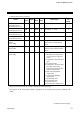
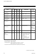
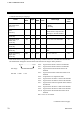
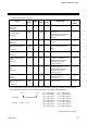
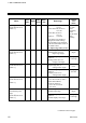
Name
Iden-
tifier
Digits
Attri-
bute
Struc-
ture
Data range
Factory
set
value
H-DO-G manipulated
output value
[H-DO-G]
D0
6 RO C −5.0 to +105.0 %
H-DO-G
DO output status
[H-DO-G]
D2
6 RO C
0 to 65535 *
Output status is expressed as
a bit image in decimal
number.
H-DO-G output limiter
(high)
[H-DO-G]
D3
6 R/W C Output limiter (low) to
105.0 %
100.0
H-DO-G output limiter
(low)
[H-DO-G]
D4
6 R/W C −5.0 % to Output limiter
(high)
0.0
H-DO-G output cycle
time
[H-DO-G]
D5
6 R/W C 1 to 100 seconds 2
H-DO-G Auto/Manual
transfer
[H-DO-G]
D6
6 R/W C
0: Auto 1: Manual
Setting will be invalid in
ON/OFF control and
heat/cool control.
0
H-DO-G manual output
value
[H-DO-G]
D7
6 R/W C
−5.0 to +105.0 %
Setting will be invalid in
ON/OFF control and
heat/cool control.
0.0
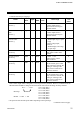
H-DO-G master channel
setting
[H-DO-G]
D8
6 R/W C
0 to The number of H-TIO-
module use channel
(0: Unused)
0
H-DO-G output ratio set
value
[H-DO-G]
D9
6 R/W C 0.001 to 9.999 1.00
* Each output status is assigned as a bit image in binary numbers. However, send data from the SR Mini
HG SYSTEM be changed to decimal ASCII code from the bit image in binary numbers.
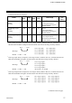
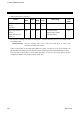
bit 15··························· bit 0
Bit image: 0000000000000000
Bit data 0: OFF 1: ON
Continued on the next page.
bit 0: CH1 (DO1) bit 8: CH9 (DO9)
bit 1: CH2 (DO2) bit 9: CH10 (DO10)
bit 2: CH3 (DO3) bit 10: CH11 (DO11)
bit 3: CH4 (DO4) bit 11: CH12 (DO12)
bit 4: CH5 (DO5) bit 12: CH13 (DO13)
bit 5: CH6 (DO6) bit 13: CH14 (DO14)
bit 6: CH7 (DO7) bit 14: CH15 (DO15)
bit 7: CH8 (DO8) bit 15: CH16 (DO16)