
Instruction manual

6. RKC COMMUNICATION
IMS01J02-E1
78
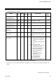
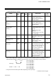
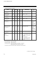
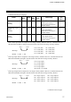
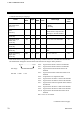
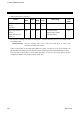
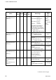
Continued from the previous page.
Name
Iden-
tifier
Digits
Attri-
bute
Struc-
ture
Data range
Factory
set
value
H-CT-A module heater
break alarm status
[H-CT-A]
AH
1 RO C
0: Normal
1: Break
2: Welding
Comprehensive alarm
status
[H-PCP-J]
AJ
6 RO U
0 to 2047 *
Alarm status is expressed as a
bit image in decimal number.
Positioning monitor
[H-TIO-K]
M8
6 RO C −5.0 to +105.0 %
Positioning output
neutral zone
[H-TIO-K]
V3
6 R/W C 0.1 to 10.0 % of motor time 2.0
Motor time
[H-TIO-K]
TJ
6 R/W C 5 to 1000 seconds 10
Integrated output limiter
[H-TIO-K]
OS
6 R/W C 100.0 to 200.0 % of motor
time
150.0
Manual positioning
output value
[H-TIO-K]
OO
6 R/W C −5.0 to +105.0 % 0.0
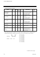
* Each alarm status is assigned as a bit image in binary numbers. However, send data from the SR Mini
HG SYSTEM be changed to decimal ASCII code from the bit image in binary numbers.
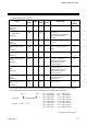
bit 15··························· bit 0
Bit image: 0000000000000000
Bit data 0: OFF 1: ON
Continued on the next page.
bit 0: Logical OR of alarm 1 status in all channels
bit 1: Logical OR of alarm 2 status in all channels
bit 2: Logical OR of burnout alarm status in all
channels
bit 3: Logical OR of heater break alarm status in all
channels
bit 4: Temperature rise completion status
bit 5: Logical OR of AI alarm 1 status in all channels
bit 6: Logical OR of AI alarm 2 status in all channels
bit 7: Logical OR of control loop break alarm status in
all channels
bit 8: Logical OR of TI alarm 1 status in all channels
bit 9: Logical OR of TI alarm 2 status in all channels
bit 10: Logical OR of TI burnout alarm status in all
channels
Bit 11 to bit 15 are unused.