
Instruction manual

6. RKC COMMUNICATION
IMS01J02-E1
74
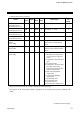
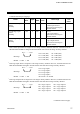
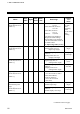
Continued from the previous page.
Name
Iden-
tifier
Digits
Attri-
bute
Struc-
ture
Data range
Factory
set
value
AO corresponding
channel setting
[H-AO-A/B]
OY
6 R/W C
1 to 20 (TIO channel)
1 to 40 (AI and TI channel)
Setting will be valid in
recorder output mode.
1
AO zooming high limit
[H-AO-A/B]
CV
6 R/W C
AO zooming low limit to
100.0 %
Setting will be valid in
recorder output mode.
100.0
AO zooming low limit
[H-AO-A/B]
CW
6 R/W C
0.0 % to AO zooming high
limit
Setting will be valid in
recorder output mode.
0.0
AO zero point correction
[H-AO-A/B]
JK
6 R/W C −5.00 to +5.00 % 0.00
AO full scale correction
[H-AO-A/B]
JL
6 R/W C −5.00 to +5.00 % 0.00
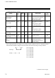
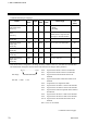
H-DI-A module input
status
[H-DI-A]
L1
6 RO M
0 to 255
a
Contact input status is
expressed as a bit image in
decimal number.
a
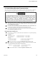
Each contact input status is assigned as a bit image in binary numbers. However, send data from the
SR Mini HG SYSTEM be changed to decimal ASCII code from the bit image in binary numbers.
bit 7·············bit 0
Bit image: 00000000
Bit data 0: OFF 1: ON
Continued on the next page.
bit 0: CH1 (DI1)
bit 1: CH2 (DI2)
bit 2: CH3 (DI3)
bit 3: CH4 (DI4)
bit 4: CH5 (DI5)
bit 5: CH6 (DI6)
bit 6: CH7 (DI7)
bit 7: CH8 (DI8)