
Instruction manual

6. RKC COMMUNICATION
IMS01J02-E1
65
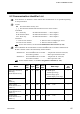
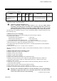
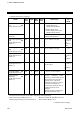
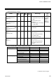
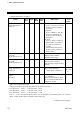
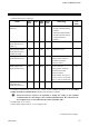
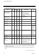
6.2 Communication Identifier List
Note that there are identifiers which indicate that communication is not possible depending
on the specification.
• Name
: Item stored in the memory area.
[ ]: The functional module name that data becomes valid is written.
• Attributes
RO: Read only SR Mini HG SYSTEM → Host computer
R/W: Read and Write SR Mini HG SYSTEM ↔ Host computer
WO: Write only SR Mini HG SYSTEM ← Host computer
• Structure
C: Data for each channel L: Data for each event input logic circuit
M: Data for each module U: Data for each unit address
For the data structure, see the 6.1.3 Communication data structure (P. 60).
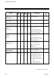
Data of identifier M1 and identifier S1 with H-TIO-/H-CIO-A module is different from
H-SIO-A module. Data is discriminated by channel number.
Identifier M1: For H-TIO-/H-CIO-A module...... Temperature measured value (PV)
For H-SIO-A module ..................... Motor speed measured value
Identifier S1: For H-TIO-/H-CIO-A module...... Temperature set value (SV)
For H-SIO-A module ..................... Motor speed set value
For the channel number, see the 8.2.9 Assignment of channels (P. 183).
Name
Iden-
tifier
Digits
Attri-
bute
Struc-
ture
Data range
Factory
set
value
Temperature measured
value (PV)
[H-TIO-, H-CIO-A]
M1
6 RO C TC/RTD input:
Within input range
Current/voltage input:
Within display scale range
Motor speed measured
value
[H-SIO-A]
Within display scale range
Alarm 1 status
[H-TIO-, H-CIO-A,
H-SIO-A]
AA
1 RO C 0: OFF 1: ON
Alarm 2 status
[H-TIO-, H-CIO-A,
H-SIO-A]
AB
1 RO C 0: OFF 1: ON
Burnout status
[H-TIO-, H-CIO-A,
H-SIO-A]
B1
1 RO C 0: OFF 1: ON
Continued on the next page.