
Instruction manual

4. WIRING
IMS01J02-E1
28
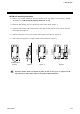
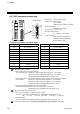
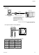
4.2.1 DO connector connection
DO connector
10
1
20
11
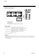
Connector pin number and signal details
Pin No. Description Pin No. Description
20
VCC (COM) +
10
VCC (COM) +
19
GND (COM) −
9
GND (COM) −
18 Unused 8 DO8
17 Unused 7 DO7
16 Unused 6 DO6
15 Unused 5 DO5
14 Unused 4 DO4
13 Unused 3 DO3
12 Unused 2 DO2
11 Unused 1 DO1
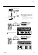
Recommended terminals
• When using the relay contact outputs
PC relay terminal: Model No.: RT1S-OD08-24V-S [Part No.: AY112402]
Model No.: RT1S-OD08-12V-S [Part No.: AY112401]
(Manufactured by Matsushita Electric Works, Ltd.)
• When using the PC terminal that interface relay or SSR (sold separately) is installed
PC terminal: Model No.: RT1-OD08-24V-S [Part No.: AY102402]
Model No.: RT1-OD08-12V-S [Part No.: AY102401]
(Manufactured by Matsushita Electric Works, Ltd.)
• When using the terminal for open collector outputs
Connector terminal: Model No.: CT1-20 [Part No.: AYT1120]
(Manufactured by Matsushita Electric Works, Ltd.)
Recommended cable and connector
• PC relay terminals/PC terminals expansion cable
Part No.: AY1584 * (Manufactured by Matsushita Electric Works, Ltd.)
* → 0: 70 mm 1: 250 mm 2: 500 mm 3: 1000 mm 5: 2000 mm
• MIL connector
Part No.: AXM120415 (Manufactured by Matsushita Electric Works, Ltd.)
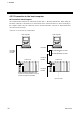
For the DO allocation, see the H-PCP-J module DO type selection (P. 100, 141).
Output type: Open collector output
N
umber of common points:
Vcc: 2 points,
GND: 2 points (8 points/common)
Isolation method:
Photocoupler isolation
Load voltage: 12 to 24 V DC
Maximum load current:
0.1 A/point, 0.8 A/common
Connector used:
MIL connector AXM220011
(Manufactured by Matsushita
Electric Works, Ltd.)