
Instruction manual

1. OUTLINE
IIMS01J02-E1
12
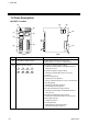
1.6 Parts Description
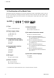
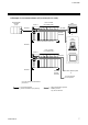
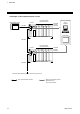
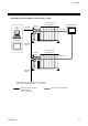
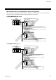
H-PCP-J module
(1)
(3)
(4)
(7)
(6)
(5)
(2)
Front Side
(10)
(11)
(8)
(9)
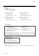
No. Name Description
(1)
Unit address setting switch Set unit address number of control unit
Setting range: 0 to 15 (0 to F, hexadecimal)
(2)
Status indication lamps RX1 (data reception) lamp [Yellow]
ON during COM.PORT1/COM.PORT2 data is
correctly received
RX2 (data reception) lamp [Yellow]
ON during COM.PORT3 data is correctly
received
EVENT lamp [Green]
ON during event operation
(Always OFF because there is not event function)
FAIL lamp [Red]
ON during abnormal operation
OFF during normal operation
TX1 (data transmission) lamp [Yellow]
ON during COM.PORT1/COM.PORT2 data is
correctly sent
TX2 (data transmission) lamp [Yellow]
ON during COM.PORT3 data is correctly sent
START lamp [Green]
ON during control
RUN lamp [Green]
Flashing during normal operation
ON during abnormal operation
Continued on the next page.
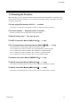
RX1 RX2 EVENT FAIL
TX1 TX2 START RUN