
Instruction manual

7. MODBUS
IMS01J02-E1
148
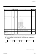
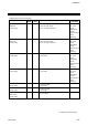
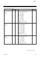
Continued from the previous page.
Name
Attri-
bute
Struc-
ture
Data range
Factory
set value
TI measured value
[H-TI-A/B/C]
RO C
Within input range
TI status
[H-TI-A/B/C]
RO C
The respective channel status is assigned to
each bit in the holding register.
bit 0: TI alarm 1 status
bit 1: TI alarm 2 status
bit 2: TI Burnout status
bit 3 to 15: Unused
Bit data 0: OFF 1: ON
[Decimal number: 0 to 7]
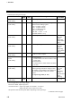
TI alarm 1 set value
[H-TI-A/B/C]
R/W C
Within input range The factory
set value
varies
depending
on the alarm
type. *
TI alarm 2 set value
[H-TI-A/B/C]
R/W C
Within input range The factory
set value
varies
depending
on the alarm
type. *
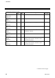
TI PV bias
[H-TI-A/B/C]
R/W C
−5.00 to +5.00 % of span
0.00
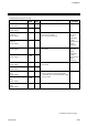
TI operation mode
transfer
[H-TI-A/B/C]
R/W C
0: Unused mode
Neither monitor nor alarm monitor is done
in this mode.
1: Normal mode
Normal mode in which monitor and alarm
are done.
1
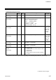
TI input range number
[H-TI-A/B/C]
R/W C
0 to 120
If the input range number is changed, all of
the settings corresponding to the channels in
the relevant module return to the default
values.
See Input range table (P. 107)
The factory
set value
varies
depending
on the
specifications
when
ordering.
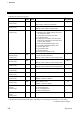
TI digital filter
[H-TI-A/B/C]
R/W C
0.0 to 100.0 seconds (0.0: OFF)
0.0
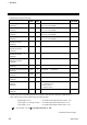
* Process high alarm: Input range (high)
Process low alarm: Input range (low)
No alarm function: Input range (high) for TI alarm 1 set value or
Input range (low) for TI alarm 2 set value
The position of the decimal point differs depending on the input range.
Continued on the next page.