
Instruction manual

7. MODBUS
IMS01J02-E1
135
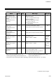
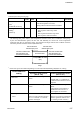
Continued from the previous page.
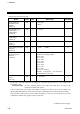
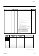
Name
Attri-
bute
Struc-
ture
Data range
Factory
set value
Decimal point position
[H-TIO-H/J, H-CIO-A,
H-SIO-A]
R/W C
0: No decimal place
1: One decimal place
2: Two decimal places
3: Three decimal places
H-TIO-H/J,
H-CIO-A: 1
H-SIO-A: 0
Input range number
[H-TIO-, H-CIO-A,
H-SIO-A]
R/W C
H-TIO-A/B/C/D/K/P: 0 to 63
H-TIO-E/F/G/R, H-CIO-A: 0 to 120
H-TIO-H/J, H-CIO-A: 0 to 12
H-SIO-A: 0 (Fixed)
If the input range number is changed, all of
the settings corresponding to the channels in
the relevant module return to the default
values.
See Input range table (P. 107)
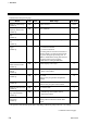
The factory
set value
varies
depending
on the
specifications
when
ordering.
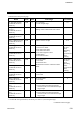
R/W C
TC/RTD input:
Setting limiter (low) to Input range (high)
Input range
(high)
Setting limiter (high)
[H-TIO-, H-CIO-A,
H-SIO-A]
C
Current/voltage input, H-SIO-A:
Setting limiter (low) to Display scale high
Display
scale high
R/W C
TC/RTD input:
Input range (low) to Setting limiter (high)
Input range
(low)
Setting limiter (low)
[H-TIO-, H-CIO-A,
H-SIO-A]
C
Current/voltage input, H-SIO-A:
Display scale low to Setting limiter (high)
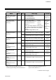
Display
scale low
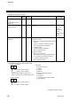
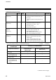
R/W C TC/RTD input:
Within input range
Input range
(high)
Input error
determination point
(high)
[H-TIO-, H-CIO-A,
H-SIO-A]
C Current/voltage input, H-SIO-A:
Within display scale range
Display
scale high
R/W C TC/RTD input:
Within input range
Input range
(low)
Input error
determination point
(low)
[H-TIO-, H-CIO-A,
H-SIO-A]
C Current/voltage input, H-SIO-A:
Within display scale range
Display
scale low
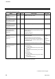
Action at input error
(high)
[H-TIO-, H-CIO-A,
H-SIO-A]
R/W C 0: Normal control
1: Manipulated output value at input error
0 *
Action at input error
(low)
[H-TIO-, H-CIO-A,
H-SIO-A]
R/W C 0: Normal control
1: Manipulated output value at input error
0
* Heat control (H-TIO-/H-CIO-A): 0 Heat/cool control (H-TIO-/H-CIO-A): 1
Position proportioning control (H-TIO-K): 0 Speed control (H-SIO-A): 0
Continued on the next page.