
Instruction manual
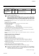

7. MODBUS
IMS01J02-E1
129
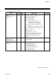
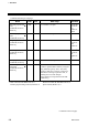
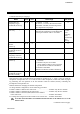
Continued from the previous page.
Name
Attri-
bute
Struc-
ture
Data range
Factory
set value
Alarm 1 set value
[H-TIO-, H-CIO-A,
H-SIO-A]
R/W C
Alarm 2 set value
[H-TIO-, H-CIO-A,
H-SIO-A]
R/W C
TC/RTD input:
Within input range or span range
Current/voltage input, H-SIO-A:
Within display scale range or span range
See Factory
set value
table of
Alarm 1/
Alarm 2
set value *
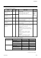
Heater break alarm
set value 1
[H-TIO-A/C/D]
R/W C 0.0 to 100.0 A or 0.0 to 30.0 A
For the current transformer (CT) input of the
H-TIO-A/C/D module.
0.0
Heater break alarm
set value 2
[H-CT-A]
R/W C 0.0 to 100.0 A or 0.0 to 30.0 A
For the current transformer (CT) input of the
H-CT-A module.
0.0
Operation mode transfer
[H-TIO-, H-CIO-A,
H-SIO-A]
R/W
C
0: Unused
If set to “Unused,” no control, monitor or
alarm monitor is performed.
1: Monitor
If set to “Monitor,” only the monitor is
performed. No control or alarm monitor is
performed.
2: Alarm
If set to “Alarm,” monitor or alarm
monitor is performed. No control is
performed.
3: Normal
Selected to normal mode to perform
control, monitor or alarm monitor.
3
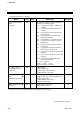
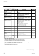
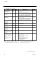
* Factory set value table of Alarm 1/Alarm 2 set value
Input type Alarm type Alarm 1 set value Alarm 2 set value
TC/RTD input
Process high alarm Input range (high limit) Input range (high limit)
Process low alarm Input range (low limit) Input range (low limit)
Deviation high alarm, Deviation
high/low alarm, Band alarm
50 °C 50 °C
Deviation low alarm
−50 °C −50 °C
No alarm function Input range (high limit) Input range (low limit)
Current/voltage input
Process high alarm 100.0 % 100.0 %
Process low alarm 0.0 % 0.0 %
Deviation high alarm, Deviation
high/low alarm, Band alarm
50 % 50 %
Deviation low alarm
−50 % −50 %
No alarm function 100.0 % 0.0 %
Continued on the next page.