
Instruction manual

7. MODBUS
IMS01J02-E1
126
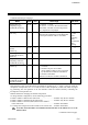
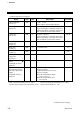
Continued from the previous page.
Name
Attri-
bute
Struc-
ture
Data range
Factory
set value
Comprehensive alarm
status
[H-PCP-J]
RO U
The respective channel status is assigned to
each bit in the holding register.
bit 0: Logical OR of alarm 1 status in all
channels
bit 1: Logical OR of alarm 2 status in all
channels
bit 2: Logical OR of burnout alarm status
in all channels
bit 3: Logical OR of heater break alarm
status in all channels
bit 4: Temperature rise completion status
bit 5: Logical OR of AI alarm 1 status in
all channels
bit 6: Logical OR of AI alarm 2 status in
all channels
bit 7: Logical OR of control loop break
alarm status in all channels
bit 8: Logical OR of TI alarm 1 status in all
channels
bit 9: Logical OR of TI alarm 2 status in all
channels
bit 10: Logical OR of TI burnout alarm
status in all channels
bit 11 to 15: Unused
Bit data 0: OFF 1: ON
[Decimal number: 0 to 2047]
Set value monitor
[H-TIO-, H-CIO-A,
H-SIO-A]
RO C
TC/RTD input:
Within input range
Current/voltage input, H-SIO-A:
Within display scale range
Temperature set value
(SV)
[H-TIO-, H-CIO-A]
R/W C
TC/RTD input:
Within input range (Within setting limiter)
Current/voltage input:
Within display scale range
(Within setting limiter)
0 *
Motor speed set value
[H-SIO-A]
R/W C
Within display scale range
(Within setting limiter)
0 *
* The position of the decimal point differs depending on the input range.
Continued on the next page.