
Instruction manual

7. MODBUS
IMS01J02-E1
115
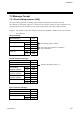
7.2 Message Format
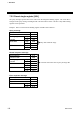
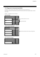
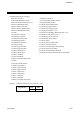
7.2.1 Read holding registers [03H]
The query message specifies the starting register address and quantity of registers to be read.
The contents of the holding registers are entered in the response message as data, divided into two
parts: the high-order 8-bit and the low-order 8-bit, arranged in the order of the register numbers.
Example: The contents of the three holding registers from 006BH to 006DH are the read out from
slave address 2.
Query message
Slave address 02H
Function code 03H
Starting No. High 00H
Low 6BH
Quantity High 00H
Low 03H
CRC-16 High 74H
Low 24H
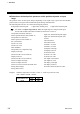
Normal response message
Slave address 02H
Function code 03H
Number of data 06H
First holding High 02H
register contents Low 2BH
Next holding High 00H
register contents Low 00H
Next holding High 00H
register contents Low 63H
CRC-16 High 50H
Low 48H
Error response message
Slave address 02H
80H + Function code 83H
Error code 03H
CRC-16 High F1H
Low 31H
First holding register address
N
umber of holding registers × 2
The setting must be between 1 (0001H)
and 125 (007DH).