
Instruction manual

7. MODBUS
IMS01J02-E1
110
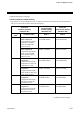
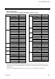
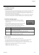
7.1.2 Function code
Function code contents
Function code
(Hexadecimal)
Function Contents
03H
Read holding registers
Measured value, control output value, Current
transformer input measured value, alarm status,
etc.
06H
Preset single register
Set value, PV bias, PID constants, alarm set
value, etc.
08H
Diagnostics (loopback test)
Loopback test
10H Preset multiple registers
Set value, PV bias, PID constants, alarm set
value, etc.
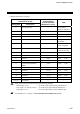
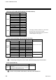
Message length of each function (Unit: byte)
Function code Function
Query message Response message
(Hexadecimal)
Min Max Min Max
03H
Read holding registers
8 8 7 255
06H
Preset single register
8 8 8 8
08H
Diagnostics (loopback test)
8 8 8 8
10H Preset multiple registers
11 209 8 8
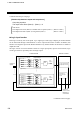
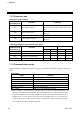
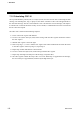
7.1.3 Communication mode
Signal transmission between the master and slaves is conducted in Remote Terminal Unit (RTU)
mode.
RTU mode
Items Contents
Data bit length 8-bit (Binary)
Start mark of message Unused
End mark of message Unused
Message length See 7.1.2 Function code
Data time interval Less than 24 bits’ time *
Error check CRC-16 (Cyclic Redundancy Check)
* When sending a command message from the master, set intervals of data configuring one
message to time shorter than the 24 bits’ time (for Modbus mode 1) or the 24 bits’ time plus
2 ms (for Modbus mode 2). If time intervals become time longer than the 24 bits’ time (for
Modbus mode 1) or the 24 bits’ time plus 2 ms (for Modbus mode 2), the relevant slave
assumes that message sending from the master is terminated to deform the message format.
As a result, the slave does not make a response.