
Instruction manual

6. RKC COMMUNICATION
IMS01J02-E1
105
Continued from the previous page.
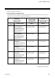
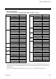
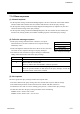
Event DI type selection
(Identifier R1 to R4)
Setting data Description
Event DI
corresponding
channel selection
(Identifier E1 to E4)
Note
0 Input always OFF
Always ON at
“Reversal” selection
1 Event DI input 1 to 80 0: OFF 1: ON
2 Event DI logic output 1 to 80 0: OFF 1: ON
3 Event DO output 1 to 72 0: OFF 1: ON
4 PCP error code
0: Not provided
1: Provided
5 Temperature rise completion
0: Rise not complete
1: Rise completed
6 PID/AT logical OR
0: All PID
1: Any one is in AT
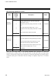
7 Alarm 1 1 to18 0: OFF 1: ON
8 Alarm 2 1 to18 0: OFF 1: ON
9 Burnout 1 to18 0: OFF 1: ON
10 Heater break alarm (HBA) 1 to18 0: OFF 1: ON
11 Control loop break alarm
(LBA)
1 to18 0: OFF 1: ON
12 AI alarm 1 1 to 36 0: OFF 1: ON
13 AI alarm 2 1 to 36 0: OFF 1: ON
14 TI alarm 1 1 to 36 0: OFF 1: ON
15 TI alarm 2 1 to 36 0: OFF 1: ON
16 TI burnout 1 to 36 0: OFF 1: ON
17 to 30 Not settable
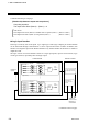
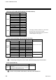
Each contact status can be monitored by the following identifier.
Digital input (1 to 8) → Event DI contact input monitor (Identifier L4)
Logic input (1 to 4)/Logic section → Event DI logic input monitor (Identifier L5)
Logic input (1 to 8) → Event DI logic output monitor (Identifier Q5)
For identifier L4, L5 and Q5, see 6.2 Communication Identifier List (P. 65).