
Instruction manual

6. RKC COMMUNICATION
IMS01J02-E1
104
Continued from the previous page.
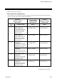
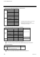
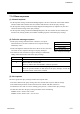
[Relationship between output and comparison]
Computing equation:
The output turns ON at (Data 2) − (Data 1) ≤ 0
This means :
The output turns ON if (Data 2) is smaller than or equal to (Data 1). {Data 2 ≤ Data 1}
The output turns OFF if (Data 2) is larger than (Data 1). {Data 2 > Data 1}
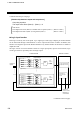
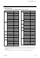
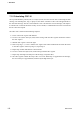
Logic input function
Each logic is built by four event inputs. Up to eight logic results (logic outputs) per H-DI-B module
can be monitored through communication or can be output from H-DO-C module. In addition, this
function can assign the input of the H-DI-B module to any channel number of the H-DO-C module to
output the result.
The logic section of event DI module consists of 4 logic input points, input reversal selection, logic
circuit type selection, input delay timer and logic output.
Digital input
8 points
Logic input 1.1
Logic input 1.2
Logic input 1.3
Logic input 1.4
Logic input 8.1
Logic input 8.2
Logic input 8.3
Logic input 8.4
Input inversion
selection
Logic circuit type
(Logic block 1)
(Logic block 8) Logic input: 32 points max./module
H-DI-B module
H-PCP-J module
Logic output monitor
Digital input monitor
Information on
other event input
module
Output from
H-DO-C module
Monitoring via
communication
Logic circuit type
Input inversion
selection
Delay
timer
Logic
output 8
Delay
timer
Logic
output 1
•
•
•
•
•
•
•
•
•
•
•
•
•
Continued on the next page.