
Instruction manual

6. RKC COMMUNICATION
IMS01J02-E1
98
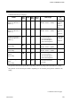
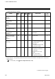
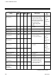
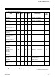
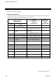
Continued from the previous page.
Name
Iden-
tifier
Digits
Attri-
bute
Struc-
ture
Data range
Factory
set
value
Number of HBA trigger
points
[H-CT-A]
DH
6 R/W U 0 to 255 times 5
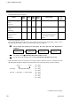
Positioning adjustment
counter
[H-TIO-K]
FV
6 R/W C 0 to 100
a
0
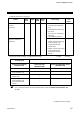
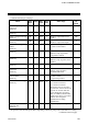
H-PCP-J module
DO de-energized
selection
[H-PCP-J]
VS
6 R/W U 0 to 255
b
Selection status is expressed
as a bit image in decimal
number.
0
a
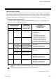
Positioning adjustment counter
The opening adjustment and the motor time are taken in. When the specified setting counter value is
input, the operations begin. (This is only valid when control is stopped.)
Always adjust the opening first and capture the motor time after the adjustment is
complete.
For details, see the Positioning adjustment counter (P. 107).
For the motor time (Identifier TJ), see 6.2 Communication Identifier List (P. 65).
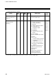
b
Each DO selection status is assigned as a bit image in binary numbers. However, send data from the
SR Mini HG SYSTEM be changed to decimal ASCII code from the bit image in binary numbers.
bit 15··························· bit 0
Bit image: 0000000000000000
Bit data 0: Energized 1: De-energized
Continued on the next page.
Capture the
motor time
Setting to normal
status
FBR opening
adjustment
Motor time
(Identifier TJ)
bit 0: DO1
bit 1: DO2
bit 2: DO3
bit 3: DO4
bit 4: DO5
bit 5: DO6
bit 6: DO7
bit 7: DO8