SR Mini HG SYSTEM Power Supply/CPU Module H-PCP-J Instruction Manual ® RKC INSTRUMENT INC.
Modbus is a registered trademark of Schneider Electric. The name of each programmable controller (PLC) means the products of each manufacturer. Company names and product names used in this manual are the trademarks or registered trademarks of the respective companies. All Rights Reserved, Copyright 2004, RKC INSTRUMENT INC.
Thank you for purchasing this RKC instrument. In order to achieve maximum performance and ensure proper operation of your new instrument, carefully read all the instructions in this manual. Please place this manual in a convenient location for easy reference. SYMBOLS WARNING : This mark indicates precautions that must be taken if there is danger of electric shock, fire, etc., which could result in loss of life or injury.
CAUTION This is a Class A instrument. In a domestic environment, this instrument may cause radio interference, in which case the user may be required to take adequate measures. This instrument is protected from electric shock by reinforced insulation. Provide reinforced insulation between the wire for the input signal and the wires for instrument power supply, source of power and loads.
CONTENTS Page 1. OUTLINE............................................................................... 1 1.1 Features ..........................................................................................................1 1.2 Handling Procedures .......................................................................................2 1.3 Checking the Products ....................................................................................3 1.4 Confirmation of the Model Code ........................
Page 6. RKC COMMUNICATION .................................................... 52 6.1 Protocol .........................................................................................................52 6.1.1 Polling ................................................................................................................ 52 6.1.2 Selecting ............................................................................................................ 57 6.1.3 Communication data structure ...............
Page 8.2.6 Scale correction ............................................................................................... 179 8.2.7 Output change rate limiter................................................................................ 181 8.2.8 Alarm hold function .......................................................................................... 182 8.2.9 Assignment of channels ................................................................................... 183 9. TROUBLESHOOTING..........
MEMO i-6 IMS01J02-E1
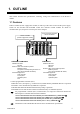
1. OUTLINE This manual describes the specifications, mounting, wiring and communication of the H-PCP-J module. 1.1 Features H-PCP-J module (Power supply/CPU module) is made up of the CPU section and the power supply section for the SR Mini HG SYSTEM control unit. H-PCP-J module includes two kinds of communication port, and protocol of each port can be changed. H-PCP-J module (Power supply/CPU module) Up to 10 function modules can be connected. SR Mini HG SYSTEM control unit COM.PORT1/COM.
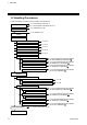
1. OUTLINE 1.2 Handling Procedures Conduct handling according to the procedure described below. See 1.3 Checking the Products (P. 3) See 1.4 Confirmation of the Model Code (P. 4) Checking the products See 3. MOUNTING (P. 20) Mounting See 4.1 WIRING (P. 25) Power supply/ground wiring Connections DO connector connection See P. 28 Connection to the host computer See P. 30 Connection to the operation panel See P. 37 Connection to the touch panel See P. 38 Multiple control unit connections See P.
1. OUTLINE 1.3 Checking the Products When unpacking your new instrument, please confirm that the following products are included. If any of the products are missing, damaged, or if your manual is incomplete, please contact RKC sales office or agent for replacement. Power supply/CPU module, H-PCP-J .... 1 module One H-PCP-J module (power supply/CPU module) is required for each control unit. Function modules .... Required number of modules Reference purchase order for description of function modules.
1. OUTLINE 1.4 Confirmation of the Model Code The model code for the instrument you received is listed below. Please confirm that you have received the correct instrument by checking the model code label, located on the left side of the module, with this list. If the product you received is not the one ordered, please contact RKC sales office or agent for replacement.
1. OUTLINE Initial code NNNN - (1) (2) (3) (4) (1) TI alarm 1 function (3) AI alarm 1 function N: No alarm function : See TI/AI alarm code table (P. 5) N: No alarm function : See TI/AI alarm code table (P. 5) (2) TI alarm 2 function (4) AI alarm 2 function N: No alarm function : See TI/AI alarm code table (P. 5) N: No alarm function : See TI/AI alarm code table (P.
1. OUTLINE 1.5 System Configuration The system configuration example that used operation panel, host computer, touch panel and programmable controller (hereafter called PLC) is shown. Example 1: PLC is used Programmable controller (PLC) H-PCP-J Function module (10 modules max.) RKC operation panel RS-422A RS-422A RS-422A RS-485 RS-232C or Host computer SR Mini HG SYSTEM control unit RS-422A H-PCP-J Function module (10 modules max.
1. OUTLINE Example 2: Current transformer (CT) monitor (PLC is used) Programmable controller (PLC) H-PCP-J H-CT-A module (10 modules max.) RKC operation panel RS-422A RS-422A RS-422A RS-485 RS-232C or Host computer SR Mini HG SYSTEM control unit RS-422A H-PCP-J H-CT-A module (10 modules max.
1. OUTLINE Example 3: RKC operation panel is used RKC operation panel H-PCP-J Function module (10 modules max.) RS-422A RS-422A RS-485 RS-232C Host computer Touch panel SR Mini HG SYSTEM control unit RS-422A H-PCP-J RS-422A Function module (10 modules max.
1. OUTLINE Example 4: Host computer or touch panel is used H-PCP-J Host computer Function module (10 modules max.) RS-422A RS-485 RKC operation panel RS-422A Touch panel SR Mini HG SYSTEM control unit RS-422A RS-485 H-PCP-J Function module (10 modules max.
1. OUTLINE Usable modules The following function modules can be used in combination with the H-PCP-J module. However, usable module is different by protocol.
1. OUTLINE Precautions for PLC communication system configuration When a system is configured by connecting a PLC, the protocol dedicated to the PLC (for temperature control) cannot be used together with the current transformer (CT) monitor.
1. OUTLINE 1.6 Parts Description H-PCP-J module (1) (8) (9) (2) (7) (10) (3) (6) (4) (11) (5) Front No. Side Name Description (1) Unit address setting switch Set unit address number of control unit Setting range: 0 to 15 (0 to F, hexadecimal) (2) Status indication lamps RX1 (data reception) lamp [Yellow] ON during COM.PORT1/COM.PORT2 data is correctly received RX2 (data reception) lamp [Yellow] ON during COM.
1. OUTLINE Continued from the previous page. No. Name Description (3) Modular connector (COM.PORT3) Connector for connection with the host computer, touch panel or operation panel (Conforming to RS-232C/RS-422A/RS-485) (4) DO connector Connector for digital output (5) Power terminals Power supply and ground terminals (6) Modular connector (COM.PORT2) Connector for the control unit addition (Conforming to RS-422A/RS-485) (7) Modular connector (COM.
2. SPECIFICATIONS Basic functions Data supervision: Operating and system data Control unit diagnosis: Function modules configuration check Self-diagnostic: Check item: ROM/RAM check Watchdog timer Power supply monitoring If error occurs in self-diagnosis, the hardware will automatically return the module outputs to the OFF position. Memory backup: Lithium battery for RAM backup, approximate 10 years life for data retention.
2. SPECIFICATIONS Digital output Number of outputs: 8 points Output type: Open collector output Number of common points: Vcc: 2 points, GND: 2 points (8 points/common) Isolation method: Photocoupler isolation Load voltage: 12 to 24 V DC Maximum load current: 0.1 A/point, 0.
2. SPECIFICATIONS Communication functions COM.PORT1/COM.PORT2 Interface: Based on RS-422A, EIA standard Based on RS-485, EIA standard Specify when ordering Connection method: RS-422A: 4-wire system, multi-drop connection RS-485: 2-wire system, multi-drop connection Protocol: • Based on ANSI X3.28 subcategory 2.
2.
2. SPECIFICATIONS COM.PORT3 Interface: Connection method: Protocol: Based on RS-232C, EIA standard Based on RS-422A, EIA standard Based on RS-485, EIA standard Specify when ordering RS-232C: Point-to-point connection RS-422A: 4-wire system, multi-drop connection RS-485: 2-wire system, multi-drop connection • Based on ANSI X3.28 subcategory 2.
2. SPECIFICATIONS Signal logic: RS-232C Signal voltage Logic +3 V or more 0 (SPACE) −3 V or less 1 (MARK) RS-422A/RS-485 Signal voltage Logic V (A) − V (B) ≥ 2 V 0 (SPACE) V (A) −V (B) ≤ −2 V 1 (MARK) Voltage between V (A) and V (B) is the voltage of (A) terminal for the (B) terminal.
3. MOUNTING This chapter describes the mounting procedures for the H-PCP-J modules. For details of the mounting procedures for other modules and the mounting position of the control unit, see the Hardware Instruction Manual (IMSRM15-E ). ! WARNING To prevent electric shock or instrument failure, always turn off the power before mounting or removing the modules. 3.1 Mounting Cautions (1) This instrument is intended to be used under the following environmental conditions.
3. MOUNTING 3.2 Dimensions External dimensions 48 4 (Unit: mm) 96 100 3.5 110 Module mounting depth The mounting depth of each module is 108 mm from the mounting surface inside the panel to the front of the module with the module mounted on the DIN rail. However, when modular connector cables are plugged in, additional depth is required. (Unit: mm) Approx.
3. MOUNTING 3.3 Mounting the Mother Block The mother block can be mounted to a panel or DIN rail. Mount the H-PCP-J module on the left side of the control unit. Panel mounting directions 1. Refer to both the panel mounting dimensions below and the external dimensions in previous section when selecting the location. (Unit: mm) 4-M3 24 24 24 77 77 24 H-PCP-J module Dimensions for multiple module mounting 2. Remove the module from the mother block. For details of removing the module, see 3.
3. MOUNTING DIN rail mounting directions 1. Remove the module mainframe from the mother block. For details of removing the module mainframe, see 3.5 Removing the Module Mainframe (P. 24). 2. Pull down both locking devices at the bottom of the mother block. (Figure 1) 3. Attach the top bracket of the mother block to the DIN rail and push the lower section into place on the DIN rail. (Figure 2) 4. Slide the locking devices up to secure the mother block to the DIN rail. (Figure 3) 5.
3. MOUNTING 3.4 Mounting the Module Mainframe 1. Place the module mainframe opening on top of the mother block tab. (Figure 1) 2. Snap the lower part of module mainframe on to the mother block. (Figure 2) A snapping sound will be heard when module mainframe is securely connected to mother block. Opening at top of module Tab at top of mother block Figure 1 Figure 2 3.
4. WIRING 4.1 Wiring ! WARNING To prevent electric shock or instrument failure, do not turn on the power until all the wiring is completed. CAUTION Power supply wiring: Use power supply as specified in power supply voltage range. Power supply wiring must be twisted and have a low voltage drop. Provide separate power supply for this instrument independent of other input/output circuits, motors, equipment and operating circuits.
4. WIRING Terminal configuration Power terminals DC + 12 24 V − AC L 12 N 12 100-120 V 200-240 V 13 AC L 13 N 13 Ground terminal 12 13 14 14 Terminal Screws Screw size: M3 Recommended tightening torque: 0.4 N⋅m (4 kgf⋅cm) Power supply 90 to 132 V AC Including power supply voltage variations (Rating: 100 to 120 V AC, Single phase 50/60 Hz) 180 to 264 V AC Including power supply voltage variations (Rating: 200 to 240 V AC, Single phase 50/60 Hz) 21.6 to 26.
4. WIRING 4.2 Connections ! WARNING To prevent electric shock or instrument failure, turn off the power before connecting or disconnecting the instrument and peripheral equipment. CAUTION Connect connectors correctly in the right position. If it is forcibly pushed in with pins in the wrong positions, the pins may be bent resulting in instrument failure. When connecting or disconnecting the connectors, do not force it too far to right and left or up and down, but move it on the straight.
4. WIRING 4.2.1 DO connector connection DO connector 20 10 11 1 Output type: Open collector output Number of common points: Vcc: 2 points, GND: 2 points (8 points/common) Isolation method: Photocoupler isolation Load voltage: 12 to 24 V DC Maximum load current: 0.1 A/point, 0.8 A/common Connector used: MIL connector AXM220011 (Manufactured by Matsushita Electric Works, Ltd.) Connector pin number and signal details Pin No. 20 19 18 17 16 15 14 13 12 11 Description Pin No.
4. WIRING Open collector output wiring example COM (+) 20 10 Load 1 DO1 ⋅ ⋅ ⋅ ⋅ ⋅ ⋅ ⋅ ⋅ ⋅ 12 to 24 V DC + − Load In using the open collector output, an external power supply of 24 V DC is required. Note that if this power supply is not connected, there will be no output from the module. 8 DO8 COM (−) 9 19 PC relay terminal connecting example H-PCP-J module Expansion cable AY1584 PC relay terminal RT1S-OD08-24V-S (Manufactured by Matsushita Electric Works, Ltd.
4. WIRING 4.2.2 Connection to the host computer Connection block diagram The communication interface for control unit are RS-232C *, RS-422A and RS-485. When using the RS-422A or RS-485, a maximum of 16 control units can be connected. However, when connecting to the computer which only has a RS-232C driver, RS-232C/RS-422A converter or RS-232C/RS-485 converter will be necessary. * RS-232C can be selected only COM. PORT3.
4. WIRING RS-232C Host computer Control unit W-BF-28 Connect to the communication connector D-SUB 9-pin connector * * Use D-SUB 25-pin modular conversion connector (Recommended type: TM12RV-64-H manufactured by HIROSE ELECTRIC CO., LTD.) when connector of host computer is D-SUB 25-pin. Connect to the [COM.PORT3] on H-PCP-J module Cable type: W-BF-28-3000 (RKC product, Sold separately) [Standard cable length: 3 m] Pin layout of modular connector (RS-232C) H-PCP-J module COM.
4. WIRING Diagram of RS-232C wiring H-PCP-J Host computer SD (TXD) 2 SD (TXD) RD (RXD) 4 RD (RXD) SG SG 3 * RS (RTS) SG 6 Shielded wire CS (CTS) *Short RS and CS within connector Customer is requested to prepare a communication cable fit for the control unit to be connected by the host computer. Connection cable W-BF-02 * and W-BF-28 * (RKC product) can use to connect host computer. * Shields of the cable are connected to SG (No. 6 pin) of the H-PCP-J connector.
4. WIRING RS-422A RS-232C/RS-422A converter COM-A (RKC product) Control unit RS-422A Connect to the [COM.PORT2] Connect to the [COM.PORT1] W-BF-02 RS-232C Connect to the [COM.PORT1] or [COM.PORT3] on H-PCP-J module Host computer D-SUB 9-pin connector * W-BF-28 * Use D-SUB 25-pin modular conversion connector (Recommended type: TM12RV-64-H manufactured by HIROSE ELECTRIC CO., LTD.) when connector of host computer is D-SUB 25-pin.
4. WIRING Pin layout of modular connector (RS-422A) COM.PORT1 1 2 3 4 5 6 H-PCP-J module COM.PORT3 R (A) R (B) SG T (B) T (A) SG SG T (A) T (B) SG R (B) R (A) 6 5 4 3 2 1 Connector pin number and signal details (RS-422A) Pin No.
4. WIRING RS-485 RS-232C/RS-485 converter Unused Control unit R(B) R(A) T/R(B) T(B) T/R(A) T(A) SG Orange White RS-485 W-BF-01 Black Blue Red SG RS-232C Connect to the [COM.PORT1] or [COM.PORT3] on H-PCP-J module Connect to the communication connector Host computer Cable type: W-BF-01-3000 (RKC product, Sold separately) [Standard cable length: 3 m] When the host computer (master) uses Windows 95/98/NT, use a RS-232C/RS-485 converter with an automatic send/receive transfer function.
4. WIRING Pin layout of modular connector (RS-485) COM.PORT1 1 2 3 4 5 6 H-PCP-J module COM.PORT3 T/R (A) T/R (B) SG SG 6 Unused 5 Unused 4 Unused Unused SG 3 T/R (B) 2 T/R (A) 1 SG Connector pin number and signal details (RS-485) Pin No.
4. WIRING 4.2.3 Connection to the operation panel For the connection cable, use the RKC product (Sold separately). Cable type: W-BF-02-3000 [Standard cable length: 3 m] Control unit RS-422A Connect to the modular connector on operation panel W-BF-02 [COM.PORT] OPM-HL4 [CN3] OPC-H Connect to the [COM.PORT1] or [COM.PORT3] on H-PCP-J module Pin layout of modular connector (RS-422A) COM.PORT1 1 2 3 4 5 6 H-PCP-J module R (A) R (B) SG T (B) T (A) SG COM.
4. WIRING 4.2.4 Connection to the touch panel RS-232C Pin layout of modular connector (RS-232C) H-PCP-J module COM.PORT3 SG 6 Unused 5 RD SG SD 4 3 2 Unused 1 Connector pin number and signal details (RS-232C) Pin No.
4. WIRING RS-422A Pin layout of modular connector (RS-422A) COM.PORT1 1 2 3 4 5 6 H-PCP-J module COM.PORT3 R (A) R (B) SG T (B) T (A) SG SG T (A) T (B) SG R (B) R (A) 6 5 4 3 2 1 Connector pin number and signal details (RS-422A) Pin No.
4. WIRING RS-485 Pin layout of modular connector (RS-485) COM.PORT1 1 2 3 4 5 6 H-PCP-J module COM.PORT3 T/R (A) T/R (B) SG SG 6 Unused 5 Unused 4 Unused Unused SG 3 T/R (B) 2 T/R (A) 1 SG Connector pin number and signal details (RS-485) Pin No.
4. WIRING 4.2.5 Multiple control unit connections When using COM.PORT1 and COM.PORT2: Connect COM.PORT2 on unit address 1 to COM.PORT1 on unit address 2. Operation panel Host computer Touch panel PLC Control unit (Unit address 1) Connect to the [COM.PORT2] on H-PCP-J module W-BF-02 Extension control unit (Unit address 2) Connect to the [COM.
4. WIRING When using COM.PORT3: Operation panel Host computer Touch panel RS-422A RS-485 Junction terminals W-BF-01 RS-422A W-BF-01 RS-485 Control unit (Unit address 1) Connect to the terminals W-BF-01 Connect to the [COM.PORT3] on H-PCP-J module Connect to the terminals Extension control unit (Unit address 2) Junction terminals or Control unit (Unit address 3) RS-422A RS-485 Cable type: W-BF-01-3000 (RKC product, Sold separately) [Standard cable length: 3 m] Connect to the [COM.
5. SETTINGS BEFORE OPERATION 5.1 Protocol Selection and Host Communication Setting ! WARNING To prevent electric shock or instrument failure, always turn off the power before setting the switch. To prevent electric shock or instrument failure, never touch any section other than those instructed in this manual. Protocol, data bit configuration, communication speed and initialize method can be set with the dip switches located in the H-PCP-J module. COM.PORT1/COM.
5. SETTINGS BEFORE OPERATION COM.PORT1/COM.PORT2 setting switch (SW2) SW2 1 OFF ON OFF ON 2 OFF OFF ON ON Data bit configuration Data 8-bit, Without parity, Stop 1-bit Data 7-bit, Odd parity, Stop 1-bit Data 7-bit, Even parity, Stop 1-bit Data 7-bit, Even parity, Stop 2-bit Factory set value: Data 8-bit, Without parity, Stop 1-bit SW2 3 OFF ON OFF ON 4 OFF OFF ON ON Communication speed 9600 bps 19200 bps 38400 bps Do not set this one Factory set value: 9600 bps Continued on the next page.
5. SETTINGS BEFORE OPERATION COM.PORT1/COM.PORT2 setting switch (SW2) SW2 5 6 7 8 OFF OFF OFF OFF Protocol RKC communication protocol (Based on ANSI X3.28 subcategory 2.5 B1) See 6. RKC COMMUNICATION (P. 52). ON OFF OFF OFF Modbus protocol See 7. MODBUS (P. 109). OFF ON OFF OFF MITSUBISHI MELSEC series special protocol AnA/AnUCPU common command (QW/QR) See PLC Communication Instruction Manual [For MITSUBISHI PLC] (IMS01J03-E ).
5. SETTINGS BEFORE OPERATION COM.
5. SETTINGS BEFORE OPERATION COM.PORT3 setting switch (SW3) SW3 7 OFF ON Modbus mode selection Modbus mode 1 (Data time interval judges time-out with 24-bit time or more.) This mode is based on Modbus RTU standard. Modbus mode 2 (Data time interval judges time-out with 24-bit time + 2 ms or more.) As time intervals between each data configuring one message become longer than the 24-bit time when sending a command message from the master, it is set when the slave does not make a response.
5. SETTINGS BEFORE OPERATION 5.2 Unit Address Setting When each control unit is multi-drop connected to host computer, set the unit address of each control unit using the unit address setting switch at the front of the H-PCP-J module. For this setting, use a small blade screwdriver. Unit address setting switch 456 CD AB E 23 F01 7 89 Setting range: 0 to 15 (0 to F: hexadecimal) H-PCP-J module Set the unit address such that it is different to the other addresses on the same line.
5. SETTINGS BEFORE OPERATION 5.3 Start-up Procedures Check prior to power on Check the following items before turning on the power to the control unit. Operation environments conform to 3.1 Mounting Cautions (P. 20). Wiring and connections conform to 4. WIRING (P. 25). Power supply voltage conforms to 2. SPECIFICATIONS (P. 14). Check after power on Check that the RUN lamps on the H-PCP-J and function modules are flashing.
5. SETTINGS BEFORE OPERATION 5.4 Communication Requirements Processing times during data send/receive The SR Mini HG SYSTEM requires the following processing times during data send/receive.
5. SETTINGS BEFORE OPERATION RS-485 (2-wire system) send/receive timing The sending and receiving of RS-485 communication is conducted through two wires; consequently, the transmission and reception of data requires precise timing.
6. RKC COMMUNICATION 6.1 Protocol RKC communication uses the polling/selecting method to establish a data link. The basic procedure is followed ANSI X3.28 subcategory 2.5, B1 basic mode data transmission control procedure (Fast selecting is the selecting method used in SR Mini HG SYSTEM). • The polling/selecting procedures are a centralized control method where the host computer controls the entire process.
6. RKC COMMUNICATION Polling procedures (1) Data link initialization Host computer sends EOT to the controllers to initiate data link before polling sequence. (2) Data sent from host computer - Polling sequence Host computer sends polling sequence with the format shown below: 1. 2. Example: 3. ENQ 0 2 M 1 ENQ Address Identifier 1. Address (2 digits) This data is a unit address of the SR Mini HG SYSTEM for polled and must be the same as the unit address set value in item 5.
6. RKC COMMUNICATION 1. STX STX is the transmission control character which indicates the start of the text transmission (identifier and data). 2. Identifier (2 digits) The identifier indicates the type of data (measured value, status and set value) sent to the host computer. See 6.2 Communication Identifier List (P. 65). 3. Data Data which is indicated by an identifier of this instrument, consisting of channel numbers, data, etc. Each channel number and data are delimited by a space (20H).
6. RKC COMMUNICATION (4) EOT send (Ending data transmission from the SR Mini HG SYSTEM) In the following cases, the SR Mini HG SYSTEM sends EOT to terminate the data link: • When the specified identifier is invalid • When there is an error in the data format • When all the data has been sent (5) No response from the SR Mini HG SYSTEM The SR Mini HG SYSTEM will not respond if the polling address is not received correctly.
6. RKC COMMUNICATION Polling procedure example (When the host computer requests data) Normal transmission Host computer send E O T 0 1 S Host computer send E N Q 1 A C K 04H 30H 31H 53H 31H 05H S T X Address Identifier S 1 0 1 4 0 0 . 0 … 02H 53H 31H 30H 31H 20H 20H 34H 30H 30H 2EH 30H Identifier Channel No.
6. RKC COMMUNICATION 6.1.2 Selecting Selecting is the action where the host computer requests one of the connected SR Mini HG SYSTEM to receive data.
6. RKC COMMUNICATION (3) Data sent from the host computer The host computer sends data for the selecting sequence with the following format: 1. STX 2. Identifier 3. 4. 6. Data ETB BCC 3. 5. 6. Data ETX BCC or 1. STX 2. Identifier If the length of send data (from STX to BCC) exceeds 128 bytes, it is divided into blocks by ETB. In this case, the succeeding divided data is sent after STX. Details for 1 to 6, see 6.1.1 Polling (P. 52).
6. RKC COMMUNICATION Selecting procedure example (when the host computer sends data) Normal transmission Host computer send E O T 0 1 S T X S 1 0 1 4 0 0 . 0 … 04H 30H 31H 02H 53H 31H 30H 31H 20H 20H 34H 30H 30H 2EH 30H Identifier Channel No.
6. RKC COMMUNICATION 6.1.3 Communication data structure Data description (Transmission/receive data structure) S T X E B T C X C ........................................................................................................ Data Part of the data above is shown below. Data for each channel Data length 6 digits 0 1 1 0 0 . Data Identifier Channel No. Space 0 , 0 2 Channel No. Comma Space ... Data ... 2 0 Channel No. Space ...
6. RKC COMMUNICATION 6.1.4 Examples of polling and selecting check programs The following is the sample program for NEC PC-9800 series computers in BASIC language for carrying out polling and selecting checking by RS-232C specification. There will be some differences in the computer languages according to the type of computer.
6.
6.
6.
6. RKC COMMUNICATION 6.2 Communication Identifier List Note that there are identifiers which indicate that communication is not possible depending on the specification. • Name : Item stored in the memory area. [ ]: The functional module name that data becomes valid is written.
6. RKC COMMUNICATION Continued from the previous page. Name IdenAttri- StrucDigits tifier bute ture Data range Factory set value Heat-side manipulated output value [H-TIO- , H-CIO-A] O1 6 RO C −5.0 to +105.0 % Cool-side manipulated output value [H-TIO- , H-CIO-A] O2 6 RO C −5.0 to +105.0 % Heater break alarm status [H-TIO-A/C/D, H-CIO-A] AC 1 RO C 0: OFF Current transformer input measured value 1 [H-TIO-A/C/D] M3 6 RO C 0.0 to 100.0 A or 0.0 to 30.
6. RKC COMMUNICATION Continued from the previous page. Name PID/AT transfer * [H-TIO- , H-CIO-A, H-SIO-A] Identifier Digits G1 1 Attri- Strucbute ture R/W C Data range Factory set value 0: PID control operation 1: AT (Autotuning) operation 0 * Autotuning (AT) is the function which automatically measures, calculates and sets the optimum PID constants according to the set temperature.
6. RKC COMMUNICATION Continued from the previous page. Name Temperature set value (SV) [H-TIO- , H-CIO-A] IdenAttri- StrucDigits tifier bute ture S1 6 R/W C Motor speed set value [H-SIO-A] Data range Factory set value TC/RTD input: Within input range (Within setting limiter) Current/voltage input: Within display scale range (Within setting limiter) 0a Within display scale range (Within setting limiter) 0a Heat-side proportional band [H-TIO- , H-CIO-A, H-SIO-A] P1 6 R/W C 0.1 to 1000.
6. RKC COMMUNICATION Continued from the previous page. Name IdenAttri- StrucDigits tifier bute ture Data range Factory set value See Factory set value table of Alarm 1/ Alarm 2 set value * Alarm 1 set value [H-TIO- , H-CIO-A, H-SIO-A] A1 6 R/W C Alarm 2 set value [H-TIO- , H-CIO-A, H-SIO-A] A2 6 R/W C Setting change rate limiter [H-TIO- , H-CIO-A, H-SIO-A] HH 6 R/W C 0.0 to 100.0 % of span/minute 0.0 Heater break alarm set value 1 [H-TIO-A/C/D] A3 6 R/W C 0.0 to 100.0 A or 0.
6. RKC COMMUNICATION Continued from the previous page. Name IdenAttri- StrucDigits tifier bute ture Data range Factory set value Operation mode transfer [H-TIO- , H-CIO-A, H-SIO-A] EI 1 R/W C Heat-side proportioning cycle time [H-TIO- , H-CIO-A] T0 6 R/W C Cool-side proportioning cycle time [H-TIO- , H-CIO-A] T1 6 R/W C 1 to 100 seconds Setting will be invalid in current/voltage output and heat control. 20 a PV bias [H-TIO- , H-CIO-A, H-SIO-A] PB 6 R/W C −5.00 to +5.
6. RKC COMMUNICATION Continued from the previous page. Factory set value Identifier Digits Initial setting mode [H-PCP-J] IN 1 R/W U 0: Normal communication Normal communication is possible. 1: Extended communication a Normal and initial setting communication are possible.
6. RKC COMMUNICATION Continued from the previous page. Name IdenAttri- StrucDigits tifier bute ture Data range Factory set value Temperature rise completion trigger 1 [H-TIO- , H-CIO-A] HS 1 R/W C 0: Unused 1: Used Do not set “1: Used” in H-TIO-H/J module and H-SIO-A module, because temperature rise completion is not judged.
6. RKC COMMUNICATION Continued from the previous page.
6. RKC COMMUNICATION Continued from the previous page. Digits AO corresponding channel setting [H-AO-A/B] OY 6 R/W C 1 to 20 (TIO channel) 1 to 40 (AI and TI channel) Setting will be valid in recorder output mode. AO zooming high limit [H-AO-A/B] CV 6 R/W C AO zooming low limit to 100.0 % Setting will be valid in recorder output mode. AO zooming low limit [H-AO-A/B] CW 6 R/W C 0.0 % to AO zooming high limit Setting will be valid in recorder output mode. 0.
6. RKC COMMUNICATION Continued from the previous page. Attri- Strucbute ture Factory set value Identifier Digits Event DO status [H-DO-C] Q3 6 RO M 0 to 255 a Contact output status is expressed as a bit image in decimal number. Event DO manual output value [H-DO-C] Q4 6 R/W M 0 to 255 a Contact output status is expressed as a bit image in decimal number.
6. RKC COMMUNICATION Continued from the previous page.
6. RKC COMMUNICATION Continued from the previous page. Digits Event DI contact input monitor [H-DI-B] L4 6 RO M 0 to 255 a Contact input status is expressed as a bit image in decimal number. Event DI logic input monitor [H-DI-B] L5 6 RO L 0 to 15 b Logic input status is expressed as a bit image in decimal number. Event DI logic output monitor [H-DI-B] Q5 6 RO M 0 to 255 c Logic output status is expressed as a bit image in decimal number.
6. RKC COMMUNICATION Continued from the previous page. Attri- Strucbute ture Factory set value Identifier Digits H-CT-A module heater break alarm status [H-CT-A] AH 1 RO C 0: Normal 1: Break 2: Welding Comprehensive alarm status [H-PCP-J] AJ 6 RO U 0 to 2047 * Alarm status is expressed as a bit image in decimal number. Positioning monitor [H-TIO-K] M8 6 RO C −5.0 to +105.0 % Positioning output neutral zone [H-TIO-K] V3 6 R/W C 0.1 to 10.0 % of motor time 2.
6. RKC COMMUNICATION Continued from the previous page. Attri- Strucbute ture Factory set value Identifier Digits H-DO-G manipulated output value [H-DO-G] D0 6 RO C −5.0 to +105.0 % H-DO-G DO output status [H-DO-G] D2 6 RO C 0 to 65535 * Output status is expressed as a bit image in decimal number. H-DO-G output limiter (high) [H-DO-G] D3 6 R/W C Output limiter (low) to 105.0 % H-DO-G output limiter (low) [H-DO-G] D4 6 R/W C −5.
6. RKC COMMUNICATION Continued from the previous page. Identifier Digits PLC scanning time setting * [H-PCP-J] ST 6 R/W U 0 to 3000 ms Integral time limiter at AT end [H-TIO- , H-CIO-A, H-SIO-A] GY 6 R/W U 1 to 3600 seconds Name Attri- Strucbute ture Data range Factory set value 10 3600 Setting will be valid in heat/cool control. * Set the PLC scanning time (time of waiting for a response from the PLC) so as to adapt to the environment used.
6. RKC COMMUNICATION 6.3 Initial Setting (Extended Communication) This section describes the initialize setting changing procedure when this system is changed to initialize setting mode. Change the setting correctly in accordance with precautions in each item. ! WARNING The Initial setting data should be set according to the application before setting any parameter related to operation.
6. RKC COMMUNICATION Name Input range number [H-TIO- , H-CIO-A, H-SIO-A] IdenAttri- StrucDigits tifier bute ture XI 6 R/W C Data range H-TIO-A/B/C/D/K/P: 0 to 63 H-TIO-E/F/G/R, H-CIO-A: 0 to 120 H-TIO-H/J, H-CIO-A: 0 to 12 H-SIO-A: 0 (Fixed) If the input range number is changed, all of the settings corresponding to the channels in the relevant module return to the default values. See Input range table (P.
6. RKC COMMUNICATION Continued from the previous page.
6. RKC COMMUNICATION Continued from the previous page. Name IdenAttri- StrucDigits tifier bute ture Data range Factory set value ON/OFF control differential gap (upper) [H-TIO- , H-CIO-A, H-SIO-A] IV 6 R/W C 0.00 to 10.00 % of span 0.02 ON/OFF control differential gap (lower) [H-TIO- , H-CIO-A, H-SIO-A] IW 6 R/W C 0.00 to 10.00 % of span 0.02 Manipulated output value at input error [H-TIO- , H-CIO-A, H-SIO-A] OE 6 R/W C −5.0 to +105.
6. RKC COMMUNICATION Continued from the previous page. Factory set value Identifier Digits Hot/Cold start selection [H-TIO- , H-CIO-A, H-SIO-A] XN 1 R/W C 0: Hot start At restarting Operation mode → Same as mode before the power failure Output value → Same as value before the power failure 1: Cold start At restarting Operation mode → Same as mode before the power failure Output value → Output limiter (low) 1 Start determination point * [H-TIO- , H-CIO-A] SX 6 R/W C 0.0 to 100.
6. RKC COMMUNICATION Continued from the previous page. Factory set value Identifier Digits Control RUN/STOP holding * [H-PCP-J] X1 1 R/W U 0: Not hold Start-up from control stop status 1: Hold Start-up from before the stop status 2: Start-up from control run status 1 Temperature rise completion hold function [H-PCP-J] EK 1 R/W U 0: Not hold 1: Hold 1 Interval time setting COM.PORT1/ COM.PORT2 [H-PCP-J] ZX 6 R/W U 0 to 100 ms 1 Interval time setting COM.
6. RKC COMMUNICATION Continued from the previous page. Name IdenAttri- StrucDigits tifier bute ture Data range Factory set value Alarm 1 differential gap [H-TIO- , H-CIO-A, H-SIO-A] HA 6 R/W U 0.00 to 10.00 % of span 0.10 Alarm 2 differential gap [H-TIO- , H-CIO-A, H-SIO-A] HB 6 R/W U 0.00 to 10.00 % of span 0.
6. RKC COMMUNICATION Continued from the previous page. Factory set value 0 Identifier Digits Alarm 1 action at input error [H-TIO- , H-CIO-A, H-SIO-A] OA 1 R/W U 0: Normal alarm action 1: Forced alarm ON when temperature measured value exceeds abnormal input trigger input. Alarm 2 action at input error [H-TIO- , H-CIO-A, H-SIO-A] OB 1 R/W U 0: Normal alarm action 1: Forced alarm ON when temperature measured value exceeds abnormal input trigger input.
6. RKC COMMUNICATION Continued from the previous page. IdenAttri- StrucDigits tifier bute ture Name This identifier is unused with this module (H-PCP-J). (H-PCP-A/B module DO type selection) VP CT channel setting [H-CT-A] ZF DO function selection [H-DO-A/B/D] LT 6 R/W U Data range 0000 to 9999 Do not set this module (H-PCP-J). Set by identifier VU (H-PCP-J module DO type selection). 6 R/W C 0 to 20 (0: Unused) Allocates the channels for H-TIO- module to the input channels of H-CT-A module.
6. RKC COMMUNICATION Continued from the previous page. Name IdenAttri- StrucDigits tifier bute ture Factory set value Data range DI function selection [H-DI-A] XK 6 R/W M 0: Unused 1: Function mode 1 − Memory area transfer (ENABLE terminal is used) After area selection setting, the actual area is changed by detecting the ENABLE edge.
6. RKC COMMUNICATION Continued from the previous page. Name IdenAttri- StrucDigits tifier bute ture Data range Factory set value The factory set value varies depending on the specifications when ordering.
6. RKC COMMUNICATION Continued from the previous page.
6. RKC COMMUNICATION Continued from the previous page. Name IdenAttri- StrucDigits tifier bute ture Data range Factory set value H-TIO-H/J, H-CIO-A: 100.0 H-SIO-A: 300 Display scale high [H-TIO-H/J, H-CIO-A, H-SIO-A] XV 6 R/W C Span 10000 or less 1 (Within −9999 to +10000) Display scale low [H-TIO-H/J, H-CIO-A, H-SIO-A] XW 6 R/W C Span 10000 or less 1 (Within −9999 to +10000) H-TIO-H/J, H-CIO-A: 0.
6. RKC COMMUNICATION Continued from the previous page. Factory set value Identifier Digits Event DO function selection [H-DO-C] XF 6 R/W C 0 to 30 * 0 Event DO corresponding channel setting [H-DO-C] XG 6 R/W C 1 to 40 * 1 Event DO mode select setting [H-DO-C] XH 6 R/W C 0 to 40 * 0 Event DO extension alarm differential gap [H-DO-C] HG 6 R/W U 0.00 to 10.00 % 0.
6. RKC COMMUNICATION Continued from the previous page.
6. RKC COMMUNICATION Continued from the previous page. Name IdenAttri- StrucDigits tifier bute ture Factory set value The factory 0 to 120 set value If the input range number is varies changed, all of the settings corresponding to the channels depending in the relevant module return on the specifications to the default values. when See Input range table ordering. (P. 107) Data range TI input range number [H-TI-A/B/C] XJ 6 R/W C TI digital filter [H-TI-A/B/C] F3 6 R/W C 0.0 to 100.0 seconds (0.
6. RKC COMMUNICATION Continued from the previous page.
6. RKC COMMUNICATION Continued from the previous page. Factory set value Identifier Digits Number of HBA trigger points [H-CT-A] DH 6 R/W U 0 to 255 times 5 Positioning adjustment counter [H-TIO-K] FV 6 R/W C 0 to 100 a 0 H-PCP-J module DO de-energized selection [H-PCP-J] VS 6 R/W U 0 to 255 b Selection status is expressed as a bit image in decimal number.
6. RKC COMMUNICATION Continued from the previous page. Name IdenAttri- StrucDigits tifier bute ture Data range Factory set value H-SIO-A input frequency at full scale [H-SIO-A] JF 6 R/W C 10 to 50000 Hz 130 H-SIO-A control range [H-SIO-A] SC 6 R/W C 0.00 to 50.00 % 10.
6. RKC COMMUNICATION Continued from the previous page.
6. RKC COMMUNICATION Event output function The event output function enables up to eight points to be output per module of unique alarms different from ordinary temperature and AI alarms (Extension alarm output function), control unit operations (Status output function) and comparison results which are output only under certain conditions (Data comparison output function). The function can be set for each channel of the H-DO-C module.
6. RKC COMMUNICATION Continued from the previous page. Status output function This function is used to output the control unit action status other than the extension alarm output in addition to the ordinary alarm output status (Alarm 1 status, etc.).
6. RKC COMMUNICATION Continued from the previous page. Data comparison output function This function is used to output the result of comparison between the measured value and measured value (or set value and set value) within the same group.
6. RKC COMMUNICATION Continued from the previous page. [Relationship between output and comparison] Computing equation: The output turns ON at (Data 2) − (Data 1) ≤ 0 This means : The output turns ON if (Data 2) is smaller than or equal to (Data 1). {Data 2 ≤ Data 1} {Data 2 > Data 1} The output turns OFF if (Data 2) is larger than (Data 1). Logic input function Each logic is built by four event inputs.
6. RKC COMMUNICATION Continued from the previous page.
6. RKC COMMUNICATION Positioning adjustment counter Item Opening adjustment Setting data (Setting counter value) 0 Normal status 1 Opening adjustment star, open-side output start (Motor time: 110 %) 2 Capture the open-side opening value after 3 seconds stop 3 Close-side output start (Motor time: 110 %) 4 Capture the close-side opening value after 3 seconds stop 5 Above data stored in H-TIO-K module 6 Hold status 7 Outputs the close-side until the positioning becomes 0 %.
6. RKC COMMUNICATION Input range table Thermocouple input (H-TIO-A/B/C/D/E/G/K/P/R, H-TI-B/C, H-CIO-A) Input type Range No. 0 0.0 to 400.0 °C 53 0 to 800 °C 1 0 to 400 °C 20 0 to 1300 °C 2 0.0 to 400.0 °C 46 0.0 to 800.0 °C 47 1 54 1 −200.0 to +300.0 °C 1 −100.0 to +400.0 °C 2 −300 to +400 °F −300.0 to +400.0 °F N 0.0 to 1300.0 °C 0 to 800 °C 6 0.0 to 2300.0 °F 0 to 1200 °C 7 49 1 50 0 to 2300 °F 82 0.0 to 2300.0 °F 8 W5Re/ 0 to 2300 °C W26Re 0.0 to 2300.
6. RKC COMMUNICATION RTD input (H-TIO-A/B/C/D/E/F/G/K/P/R, H-TI-A/B, H-CIO-A) Input type Range No. 0.0 to 400.0 °C 59 0 to 400 °C 38 −200 to +200 °C 39 −200.0 to +200.0 °C JPt100 58 −50.00 to +150.00 °C 1 106 −300 to +900 °F 41 0 to 800 °F 40 0.0 to 800.0 °F −300.0 to +900.0 °F 60 2 104 0.0 to 400.0 °C 62 0 to 400 °C 42 −200 to +200 °C 43 −200.0 to +200.0 °C Pt100 −50.00 to +150.00 °C 61 1 −300 to +1200 °F 45 0 to 800 °F 44 0.0 to 800.0 °F −300.0 to +1200.
7. MODBUS 7.1 Protocol The master controls communication between master and slave. A typical message consists of a request (query message) sent from the master followed by an answer (response message) from the slave. When master begins data transmission, a set of data is sent to the slave in a fixed sequence. When it is received, the slave decodes it, takes the necessary action, and returns data to the master. 7.1.
7. MODBUS 7.1.2 Function code Function code contents Function code (Hexadecimal) Function Contents 03H Read holding registers Measured value, control output value, Current transformer input measured value, alarm status, etc. 06H Preset single register Set value, PV bias, PID constants, alarm set value, etc. 08H Diagnostics (loopback test) Loopback test 10H Preset multiple registers Set value, PV bias, PID constants, alarm set value, etc.
7. MODBUS 7.1.4 Slave responses (1) Normal response • In the response message of the Read Holding Registers, the slave returns the read out data and the number of data items with the same slave address and function code as the query message. • In the response message of the Preset Single Register and Diagnostics (Loopback test), the slave returns the same message as the query message.
7. MODBUS 7.1.5 Calculating CRC-16 The Cyclic Redundancy Check (CRC) is a 2 byte (16-bit) error check code. After constructing the data message, not including start, stop, or parity bit, the master calculates a CRC code and appends this to the end of the message. The slave will calculate a CRC code from the received message, and compare it with the CRC code from the master. If they do not coincide, a communication error has occurred and the slave does not respond.
7. MODBUS The flow chart of CRC-16 START FFFFH → CRC Register CRC Register ⊕ next byte of the message → CRC Register 0→n Shift CRC Register right 1 bit Carry flag is 1 No Yes CRC Register ⊕ A001H → CRC Register n+1→n No n>7 Yes No Is message complete ? Yes Reverse with high-order byte and low-order byte of CRC Register. END The ⊕ symbol indicates an exclusive OR operation. The symbol for the number of data bits is n.
7. MODBUS Example of a CRC calculation in the ‘C’ language This routine assumes that the data types ‘uint16’ and ‘uint8’ exists. Theses are unsigned 16-bit integer (usually an ‘unsigned short int’ for most compiler types) and unsigned 8-bit integer (unsigned char). ‘z_p’ is a pointer to a Modbus message, and z_messaage_length is its length, excluding the CRC. Note that the Modbus message will probably contain NULL characters and so normal C string handling techniques will not work.
7. MODBUS 7.2 Message Format 7.2.1 Read holding registers [03H] The query message specifies the starting register address and quantity of registers to be read. The contents of the holding registers are entered in the response message as data, divided into two parts: the high-order 8-bit and the low-order 8-bit, arranged in the order of the register numbers. Example: The contents of the three holding registers from 006BH to 006DH are the read out from slave address 2.
7. MODBUS 7.2.2 Preset single register [06H] The query message specifies data to be written into the designated holding register. The write data is arranged in the query message with high-order 8-bit first and low-order 8-bit next. Only R/W holding registers can be specified. Example: Data is written into the holding register 00C8H of slave address 1.
7. MODBUS 7.2.3 Diagnostics (Loopback test) [08H] The master’s query message will be returned as the response message from the slave. This function checks the communication system between the master and slave (SR Mini HG SYSTEM control unit).
7. MODBUS 7.2.4 Preset multiple registers [10H] The query message specifies the starting register address and quantity of registers to be written. The write data is arranged in the query message with high-order 8-bit first and low-order 8-bit next. Only R/W holding registers can be specified. Example: Data is written into the two holding registers from 00C8H to 00C9H of slave address 1.
7. MODBUS 7.3 Communication Data 7.3.1 Data configuration The numeric range of data used in Modbus protocol is 0000H to FFFFH. Only the set value within the setting range is effective. FFFFH represents −1. Data processing with decimal points Data with decimal points The Modbus protocol does not recognize data with decimal points during communication.
7. MODBUS Data with 3 digits below decimal point H-DO-G output ratio set value Example: Cascade gain When heater break alarm set value 1 is 20.0 A, 20.
7. MODBUS Continued from the previous page.
7. MODBUS Data whose decimal point’s presence and/or position depends on input range The position of the decimal point changes depending on the input range type because the Modbus protocol does not recognize data with decimal points during communication. The following data can have one of three decimal point positions: No digit below decimal point, 1 digit below decimal point, 2 digits below decimal point For details, see Input range table (P. 107).
7. MODBUS 7.3.2 Data processing precautions With Modbus protocol, the maximum number of channels per slave address is 20. The accessible data (holding register) address range is from 0000H to 1FFFH. If data exceeding the 1FFFH is accessed, an error response message is returned. Do not write data to any address which is not described in a list of data maps. Initialize the module after changing to stop the control. Read data of unused channel and undefined address is “0.
7. MODBUS 7.3.3 Communication data list • Name : Item stored in the memory area. [ ]: The functional module name that data becomes valid is written.
7. MODBUS Continued from the previous page. Name Status [H-TIO- , H-CIO-A, H-SIO-A] Attribute RO StrucData range ture The respective channel status is assigned to C each bit in the holding register. bit 0: Alarm 1 status bit 1: Alarm 2 status bit 2: Burnout status bit 3: Heater break alarm status (OR operation of the H-TIOmodule and H-CT-A module.
7. MODBUS Continued from the previous page. Name Comprehensive alarm status [H-PCP-J] Attribute RO StrucData range ture The respective channel status is assigned to U each bit in the holding register.
7. MODBUS Continued from the previous page. Name PID/AT transfer * [H-TIO- , H-CIO-A, H-SIO-A] Attribute R/W StrucData range ture C 0: PID control operation 1: AT (Autotuning) operation Factory set value 0 * Autotuning (AT) is the function which automatically measures, calculates and sets the optimum PID constants according to the set temperature.
7. MODBUS Continued from the previous page. Name Heat-side proportional band [H-TIO- , H-CIO-A, H-SIO-A] Attribute R/W StrucData range ture C 0.1 to 1000.0 % of span Factory set value H-TIO- , H-CIO-A: 3.0 H-SIO-A: 300.0 Cool-side proportional band [H-TIO- , H-CIO-A] R/W C 0.1 to 1000.
7. MODBUS Continued from the previous page. Name Alarm 1 set value [H-TIO- , H-CIO-A, H-SIO-A] Attribute R/W StrucData range ture TC/RTD input: C Within input range or span range Current/voltage input, H-SIO-A: Within display scale range or span range C Factory set value See Factory set value table of Alarm 1/ Alarm 2 set value * Alarm 2 set value [H-TIO- , H-CIO-A, H-SIO-A] R/W Heater break alarm set value 1 [H-TIO-A/C/D] R/W C 0.0 to 100.0 A or 0.0 to 30.
7. MODBUS Continued from the previous page. Name Heat-side proportioning cycle time [H-TIO- , H-CIO-A] Attribute R/W StrucData range ture C 1 to 100 seconds Setting will be invalid in current/voltage output. Factory set value 20 a Cool-side proportioning cycle time [H-TIO- , H-CIO-A] R/W C 1 to 100 seconds Setting will be invalid in current/voltage output and heat control.
7. MODBUS Continued from the previous page. Name Temperature rise completion trigger [H-TIO- , H-CIO-A] Attribute R/W StrucData range ture 0: Unused 1: Used 1 C Do not set “1: Used” in H-TIO-H/J module and H-SIO-A module, because temperature rise completion is not judged. Factory set value 0 CT channel setting [H-CT-A] R/W C 0 to 20 (0: Unused) Allocates the channels for H-TIO- module to the input channels of H-CT-A module. The factory set value varies depending on the specifications when ordering.
7. MODBUS Continued from the previous page. Name Cascade ON/OFF [H-CIO-A] Attribute R/W StrucData range ture 0: OFF 1: ON C Setting will be valid in master channel. Factory set value 0 Cascade gain [H-CIO-A] R/W C −9.999 to +10.000 As the cascade gain is valid only in the slave channel, the polling or selecting of the same value is made also in the master channel. 1.000 Cascade bias [H-CIO-A] R/W C −99.99 to +100.
7. MODBUS Continued from the previous page. Name Output limiter (low) [For heat/cool control: Cool-side output limiter (high)] [H-TIO- , H-CIO-A, H-SIO-A] Attribute R/W StrucData range ture [Heat control, Position proportioning control C and Speed control] −5.0 % to Output limiter (high) [Heat/cool control] Cool-side output limiter (high): −5.0 % to +105.0 % Cool-side output limiter (low): −5.0 % (fixed) Factory set value 0.
7. MODBUS Continued from the previous page. Name H-SIO-A control range [H-SIO-A] Attribute R/W StrucData range ture C 0.00 to 50.00 % Factory set value 10.
7. MODBUS Continued from the previous page.
7. MODBUS Continued from the previous page. Name AT bias [H-TIO- , H-CIO-A, H-SIO-A] Attribute R/W StrucData range ture C Within ± input span range Factory set value 0* ON/OFF control differential gap (upper) [H-TIO- , H-CIO-A, H-SIO-A] R/W C 0.00 to 10.00 % of span 0.02 ON/OFF control differential gap (lower) [H-TIO- , H-CIO-A, H-SIO-A] R/W C 0.00 to 10.00 % of span 0.02 Manipulated output value at input error [H-TIO- , H-CIO-A, H-SIO-A] R/W C −5.0 to +105.
7. MODBUS Continued from the previous page. AttriName bute Start determination R/W 1 point [H-TIO- , H-CIO-A] Control RUN/STOP holding 2 [H-PCP-J] 1 R/W StrucData range ture 0.0 to 100.0 % of span (Deviation setting C from the temperature set value) Setting will be invalid in H-SIO-A module. U Factory set value 3.
7. MODBUS Continued from the previous page. Name Temperature rise completion hold function [H-PCP-J] Attribute R/W Structure U 0: Not hold 1: Hold Factory set value 1 Data range Interval time setting COM.PORT1/ COM.PORT2 [H-PCP-J] R/W U 0 to 100 ms 1 Interval time setting COM.
7. MODBUS Continued from the previous page. Name PV bias unit selection [H-TIO- , H-CIO-A, H-SIO-A] Attribute R/W StrucData range ture 0: % (of span) U 1: Unit of input range Factory set value 0* 1 to 3600 seconds 3600 Integral time limiter at AT end [H-TIO- , H-CIO-A, H-SIO-A] R/W Alarm 1 differential gap [H-TIO- , H-CIO-A, H-SIO-A] R/W U 0.00 to 10.00 % of span 0.10 Alarm 2 differential gap [H-TIO- , H-CIO-A, H-SIO-A] R/W U 0.00 to 10.00 % of span 0.
7. MODBUS Continued from the previous page. Attri- StrucName Data range bute ture R/W U Number of alarm delay 0 to 255 times times [H-TIO- , H-CIO-A, H-SIO-A] R/W M DO function selection 00 to 88 * [H-DO-A/B/D] DI function selection [H-DI-A] R/W M Factory set value 0 The factory set value varies depending on the specifications when ordering.
7. MODBUS Continued from the previous page.
7. MODBUS Continued from the previous page. AttriName bute Cascade tracking R/W [H-CIO-A] StrucData range ture 0: Not provided M Cascade monitored value becomes zero. 1: Provided Cascade monitored value just before is hold.
7. MODBUS Continued from the previous page. AttriName bute Positioning adjustment R/W counter [H-TIO-K] Structure C 0 to 100 * Factory set value 0 Data range H-CT-A module heater break alarm status [H-CT-A] RO C 0: Normal 1: Break 2: Welding H-DI-A module input status [H-DI-A] RO M The respective channel status is assigned to each bit in the holding register.
7. MODBUS Continued from the previous page. Attri- StrucName Data range bute ture RO C −5.0 to +105.0 % H-DO-G manipulated output value [H-DO-G] R/W C Output limiter (low) to 105.0 % H-DO-G output limiter (high) [H-DO-G] R/W C −5.0 % to Output limiter (high) H-DO-G output limiter (low) [H-DO-G] R/W C 1 to 100 seconds H-DO-G output cycle time [H-DO-G] R/W C 0 to The number of H-TIO- module use H-DO-G master channel setting channel (0: Unused) [H-DO-G] R/W C 0.001 to 9.
7. MODBUS Continued from the previous page. Attri- StrucName Data range bute ture RO C AI measured value Within display scale range * [H-AI-A/B] RO C AI status The respective channel status is assigned to [H-AI-A/B] each bit in the holding register. bit 0: AI alarm 1 status bit 1: AI alarm 2 status bit 2 to 15: Unused Bit data 0: OFF 1: ON [Decimal number: 0 to 3] Factory set value AI alarm 1 set value [H-AI-A/B] R/W C Within display scale range * Process high alarm: 100.0 Process low alarm: 0.
7. MODBUS Continued from the previous page. Attri- StrucName Data range bute ture 0: 0 to 10 mV DC AI input range number R/W C 1: −10 to +10 mV DC [H-AI-A/B] 2: 0 to 100 mV DC 3: −100 to +100 mV DC 4: 0 to 1 V DC 5: −1 to +1 V DC 6: 0 to 5 V DC 7: 1 to 5 V DC 8: −5 to +5 V DC 9: 0 to 10 V DC 10: −10 to +10 V DC 11: 0 to 20 mA DC 12: 4 to 20 mA DC Voltage (low) input group: 0 to 8 Voltage (high) input group: 9 to 10 Current input group: 11 to 12 An input type change may only be made within the input groups.
7. MODBUS Continued from the previous page. Attri- StrucName Data range bute ture U AI alarm 1 type 0: Process high alarm R/W selection 1: Process low alarm [H-AI-A/B] 2 to 6: No alarm function Factory set value The factory set value varies depending on the specifications when ordering. AI alarm 2 type selection [H-AI-A/B] R/W U 0: Process high alarm 1: Process low alarm 2 to 6: No alarm function The factory set value varies depending on the specifications when ordering.
7. MODBUS Continued from the previous page. Attri- StrucName Data range bute ture TI measured value RO C Within input range [H-TI-A/B/C] Factory set value TI status [H-TI-A/B/C] RO C The respective channel status is assigned to each bit in the holding register.
7. MODBUS Continued from the previous page. AttriName bute TI alarm 1 differential gap R/W [H-TI-A/B/C] StrucData range ture 0.00 to 10.
7. MODBUS Continued from the previous page. Attri- StrucName Data range bute ture AO output value monitor Display scale range * RO C [H-AO-A/B] Data will be valid in manual mode. Factory set value AO output set value [H-AO-A/B] R/W C Display scale range * Setting will be valid in manual mode.
7. MODBUS Continued from the previous page. AttriName bute Event DI contact input RO monitor [H-DI-B] StrucData range ture The respective channel status is assigned to M each bit in the holding register.
7. MODBUS Continued from the previous page.
7. MODBUS Continued from the previous page. AttriName bute Event DO status RO [H-DO-C] StrucData range ture The respective channel status is assigned to M each bit in the holding register.
7. MODBUS 7.4 Data Map 7.4.1 Reference to data map This data map summarizes the data addresses, channels and names that can be used with Modbus protocol. For details on each data range, see 7.3.3 Communication data list (P. 124). (2) (1) Address 0000H ( ⋅⋅ ⋅ ⋅⋅ ⋅ 0013H ( CH 0) CH1 ⋅⋅ ⋅ ⋅⋅ ⋅ 19) CH20 Name Temperature measured value (PV) H-TIO- , H-CIO-A Motor speed measured value H-SIO-A (3) (4) (1) Address: Address of data is written with hexadecimal number. Characters in ( ) are decimal number.
7. MODBUS 7.4.
7.
7. MODBUS Continued from the previous page.
7.
7. MODBUS Continued from the previous page.
7. MODBUS Continued from the previous page.
7.
7.
7.
7.
7.
7.
7.
8. FUNCTIONS 8.1 Output Ratio Output ratio function multiplies value (gradient) set with output ratio in manipulated output value of master channel (Temperature control module H-TIO- ), and it is function to output the consequence as manipulated output value from slave channel (Digital output module H-DO-G). Other than H-PCP-J module, H-TIO- module and H-DO-G module are requirement to do output ratio function.
8. FUNCTIONS Output ratio action Manipulated output value of master channel and slave channel are output within the output limiter range. Master channel (H-TIO module) Manipulated output value of master channel Output limiter (high limit) Output limiter (low limit) 0% PID computation result 100 % Slave channel (H-DO-G module) Manipulated output value of slave channel Output ratio set value: 2.000 Output limiter (high limit) Output ratio set value: 1.000 Output ratio set value: 0.
8. FUNCTIONS Assignment of the master channels It is possible to assign the master channel corresponding to the slave channel if in the same unit. The master channel is assigned by “H-DO-G master channel setting.” H-DO-G master channel setting Setting range: 0 to The number of H-TIO- module use channel (0: Unused) Example: Setting in the following system configuration. H-PCP-J module ........................... 1 H-TIO-B module (2 channels) ....... 4 (Master channel 1 to 8) H-DO-G module (16 channels) ..
8. FUNCTIONS H-DO-G master channel setting example Slave channel No. (H-DO-G module) H-DO-G master channel setting Slave channel No. (H-DO-G module) H-DO-G master channel setting 1 2 3 4 5 6 7 8 9 10 11 12 13 14 15 16 1 1 2 2 2 2 2 3 3 3 3 3 4 4 4 4 17 18 19 20 21 22 23 24 25 26 27 28 29 30 31 32 5 5 5 6 6 6 7 7 7 8 8 8 0 0 0 0 For the H-TIO- module, see the Hardware Instruction Manual (IMSRM15-E ). For the H-DO-G module, see the H-DO-G Instruction Manual (IMS01K01-E ).
8. FUNCTIONS 8.2 Speed Control Speed control function inputs pulse from rotary encoder, and motor speed is controlled. Other than H-PCP-J module, H-SIO-A module are requirement to do speed control function.
8. FUNCTIONS 8.2.1 Display scale This function scales the display range of the input value between −9999 to +10000. However, the maximum span is 10000. H-SIO-A input frequency at full scale: Sets the frequency of encoder when display scale high value (full scale) is displayed. Setting rage: 10 to 50000 Hz Display scale high: Sets the high limit value (full scale) of display scale.
8. FUNCTIONS 8.2.2 Measuring method Can be selected periodic computation method or pulse count method. Periodic computation method Frequency is obtained by measuring the time required for certain pulse intervals. The number of measured pulses can be set in the pulse range of 1 to 1000 by setting divide ratio. Setting range H-SIO-A divide ratio: 1 to 1000 Example: When divide ratio is set to 3.
8. FUNCTIONS 8.2.3 Output scale This function scales the output range between −9999 to +10000. H-SIO-A output scale high: Sets the value equivalent to display scale of control output high limit. Setting rage: H-SIO-A output scale low to 10000 H-SIO-A output scale low: Sets the value equivalent to display scale of control output low limit. Setting rage: −9999 to H-SIO-A output scale high Example: Output scale setting when the control output value is 9 V DC at maximum motor speed of 1000 mm/min.
8. FUNCTIONS 8.2.5 Controls This instrument controls with open loop control or PID control (closed loop control). (1) Open loop control In a deviation between the motor speed measured value and set value is larger than the H-SIO-A control range set value, or the H-SIO-A open/closed loop control transfer is “1: Open loop control,” the instrument is in open loop control, thereby outputting a constant control output value corresponding to the motor speed set value.
8. FUNCTIONS (2) PID Control (Closed loop control) If a deviation between the motor speed measured value and set value is within the control range set value, and the H-SIO-A open/closed loop control transfer is “0: Closed loop control,” the instrument performs PID control. PI control (factory set value, derivative time: 0) is recommended in case of speed control.
8. FUNCTIONS Control response parameters This is the function of enabling the setting of response to set value change in select any one of 3 steps (Slow, Medium, Fast) in PID control. In order to achieve faster controlled object response to set value change, select Fast. However, slight overshoot is unavoidable when selecting Fast. Depending on the controlled object, specify Slow if overshoot should be avoided.
8. FUNCTIONS 8.2.6 Scale correction This is the function of correcting the motor speed measured value and control output when the motor speed measured value differs from the actually measured value or motor speed set value differs from the actually measured value. SR Mini HG SYSTEM Control output (Current/voltage output) Motor speed set value Motor Be different Actual measured value Be different Motor speed measured value : When scale correction was executed, it is revised.
8. FUNCTIONS Example: Correction in the following value. Control output: Display scale high: Display scale low: Output scale high: Output scale low: Voltage output 0 to 10 V DC 300 mm/min 0 mm/min 400 mm/min 0 mm/min Motor speed set value: 250 mm/min Motor speed measured value: 245 mm/min Actual measured value: 240 mm/min 6.51 V DC after scale correction Voltage output 6.
8. FUNCTIONS 8.2.7 Output change rate limiter The output change rate limiter limits the variation of manipulated output (MV) for a time unit. You can set an output variation, and control the output, when your object requires to avoid sudden variation. The output variation limiter is particularly effective when a sudden variation may cause the controller to crash, or when it may cause a large current. Also, it is very effective when you are dealing with current output or voltage output.
8. FUNCTIONS 8.2.8 Alarm hold function In the alarm hold function, the alarm function is kept invalid even if the motor speed measured value is in the alarm range when the power is on or the operation mode is switched to RUN from STOP. The alarm function is held until it passes with H-SIO-A alarm hold cancel time. H-SIO-A alarm hold cancel time: Set the time which cancels hold action of alarm.
8. FUNCTIONS 8.2.9 Assignment of channels Channel number of H-SIO-A modules uses the same kind of channel number as H-TIO- modules and H-CIO-A modules. If the H-SIO-A modules are mounted together with H-TIO- modules and H-CIO-A modules, the channel numbers are continued. Channel number is decided in order automatically from the left. Example: Examples of channel number assigning in the following system configuration. H-PCP-J module ......1 H-TIO-B module........2 H-SIO-A module .....1 H-CIO-A module ......
9. TROUBLESHOOTING This section lists some basic causes and solutions to be taken when any problem would arise in this instrument. If you can not solve a problem, please contact RKC sales office or the agent, on confirming the type name and specifications of the product. If the instrument is necessary to be replaced, observe the following warning. ! WARNING To prevent electric shock or instrument failure, always turn off the system power before replacing the instrument.
9. TROUBLESHOOTING H-PCP-J module Problem RUN lamp does not light up Probable cause Solution Power not being supplied Check external breaker etc.
9.
9.
9.
9. TROUBLESHOOTING Continued from the previous page. Problem TX1 (data transmission) lamp and RX1 (data reception) lamp are Probable cause Solution Setting of PLC becomes write inhibit Setting of PLC is turned into write enable (Write enable in RUN, shift to monitor mode, etc.
10. ASCII 7-BIT CODE TABLE This table is only for use with RKC communication.
The first edition: SEP.
RKC INSTRUMENT INC. HEADQUARTERS: 16-6, KUGAHARA 5-CHOME, OHTA-KU TOKYO 146-8515 JAPAN PHONE: 03-3751-9799 (+81 3 3751 9799) E-mail: info@rkcinst.co.jp FAX: 03-3751-8585 (+81 3 3751 8585) IMS01J02-E1 SEP.