
Instruction manual


3. DESCRIPTION OF EACH MODULES
IMSRM15-E6
76
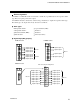
[Example]
When the temperature alarm 1 and heater break alarms of the H-TIO-B module are output
independently for each channel by the H-DO-A module.
Block 1 (DO1 to 4): Temperature alarm 1 Block 3 (DO9 to 12): Temperature alarm 1
Block 2 (DO5 to 8): Temperature alarm 1 Block 4 (DO13 to 16): Heater break alarm
No assigned channel can be skipped. Terminals corresponding to the channel which does not
use various alarms become vacant (unused).
Each alarm can be assigned from the dedicated host computer via communication.
For details on alarm selection, refer to SR Mini/SR Mini HG SYSTEM Supplementary
Information Initialize Settings [Extended Communications] (IMSRM07-E
).
H-TIO-B module
H-DO-A module
CH1
CH2
CH3
CH4
CH5
CH6
CH7
CH8
CH9
CH10
CH11
CH12
Temperature alarm 1 CH1 to 4
Block 1 (DO1 to 4)
Temperature alarm 1 CH9 to 12
Block 3 (DO9 to 12)
Temperature alarm 1 CH5 to 8
Block 2 (DO5 to 8)
Heater break alarm CH1 to 4
Block 4 (DO13 to 16)
The assignment of channel
number of H-TIO-B modules to
the terminals of H-DO-A
modules is done automatically
from the top of the terminal of
the H-DO-A module installed at
the far left.