
Instruction manual


3. DESCRIPTION OF EACH MODULES
IMSRM15-E6
69
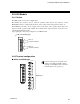
(2) Digital event input function (H-DI-B)
Logic input function
Each logic is built by four event inputs. Up to eight logic results (logic outputs) per H-DI-B module
can be monitored through communication or can be output from event output module (H-DO-C).
In addition, this function can assign the input of the H-DI-B module to any channel number of the
H-DO-C module to output the result.
The logic section of event H-DI-B module consists of 4 logic input points, input reversal selection,
logic circuit type selection, input delay timer and logic output.
H-DI-B module (event input function) and the H-PCP module with the specification of
ladder communication cannot be selected at the same time.
Each event input can be assigned from the dedicated host computer via communication.
For details on event input selection, refer to SR Mini/SR Mini HG SYSTEM Supplementary
Information Initialize Settings [Extended Communications] (IMSRM07-E
).
Digital input
8 points
Lo
g
ic in
p
ut 1.1
Lo
g
ic in
p
ut 1.2
Lo
g
ic in
p
ut 1.3
Lo
g
ic in
p
ut 1.4
Lo
g
ic in
p
ut 8.1
Lo
g
ic in
p
ut 8.2
Lo
g
ic in
p
ut 8.3
Lo
g
ic in
p
ut 8.4
Input inversion
selection
Logic circuit type
Delay
timer
Logic
out
p
ut 1
(
Lo
g
ic block 1
)
(
Lo
g
ic block 8
)
Lo
g
ic in
p
ut: 32
p
oints max./module
H-DI-B module
PCP module
Logic output monitor
Digital input monitor
Information on
other event input
module
Output from
H-DO-C module
Monitoring via
communication
The desired channel No. of the digital event input module is assigned to the respective logic
input.
Logic output can be re-assigned to the input of the logical block.
Logic circuit type
Input inversion
selection
Delay
timer
Logic
out
p
ut 8