
Instruction manual


3. DESCRIPTION OF EACH MODULES
IMSRM15-E6
38
3.3.3 Functional description
Output function
FAIL output
The FAIL output is output when a problem occurs in the CPU operation and the FAIL lamp will light
at the same time. Use this output for FAIL monitoring or for signal output to an external PLC, etc.
Number of outputs: 1 point
Output type: Relay contact output, 1a contact (Open at error occurrence)
[Rating: 250 V AC, 0.1 A (Resistive load)]
(CE/UL/cUL (or CSA) approved instrument: 30 V DC, 0.1 A)
When the FAIL condition occurs in any of the function modules in the control unit, the FAIL
output will also be output. However in this situation, the FAIL lamp will not light.
If the composition of the control unit is changed (add or delete a function module, or change
the arrangement of the modules, or replace a module with a different model) without the
module initialization, the FAIL output will be output. However in this situation the FAIL
lamp will not light either.
For details on how to initialize the module, refer to SR Mini/SR Mini HG SYSTEM
Supplementary Information Initialize Settings [Extended Communications]
(IMSRM07-E
).
Digital output (DO) [H-PCP-A and H-PCP-B]
The digital outputs (DO) can be selected from the alarm 1, alarm 2, heater break alarm (HBA),
burnout alarm, temperature rise completion, loop break alarm (LBA), AI alarm 1 or AI alarm 2.
In addition, function of digital output (DO) selects in operation panel or host communication.
Number of outputs: 4 points (H-PCP-A type), 2 points (H-PCP-B type)
Output type: Relay contact output, 1a contact (Closed at alarm occurrence)
[Rating: 250 V AC, 0.1 A (Resistive load)]
(CE/UL/ cUL (or CSA) approved instrument: 30 V DC, 0.1 A)
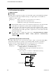
Open collector output
[Load voltage: 12 to 24 V DC, 0.1 A (Maximum load current)]
Open collector output wiring example
12 to 24 V DC
OUT4
OUT1
+
+
+
-
-
-
Load
Load