
Instruction manual


3. DESCRIPTION OF EACH MODULES
IMSRM15-E6
31
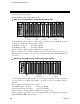
3.2.2 Parts description
H-PCP-A/B module
No. Name Description
(1) Unit address setting switch Set control unit slave address number
Setting range: 0 to 15 (0 to F, hexadecimal)
(2) RX (data reception) lamp [Yellow] ON when data is correctly received
(3) TX (data transmission) lamp [Yellow] ON when data is correctly sent
(4) FAIL lamp [Red] ON during abnormal operation
OFF during normal operation
(5) RUN lamp [Green] Flashing during normal operation
(6) Modular connector 1 RS-232C or RS-422A connection with the host
computer or operation panel
(7) Modular connector 2 RS-422A connection with other control unit
(8) Terminals Ground, power supply, FAIL output, digital input
and digital output terminals
(9) Mother block Module DIN rail mounting connector
(10) Module connector Connector for power supply and bus connection
(10) Module connector
(9) Mother block
Side
(1) Unit address setting switch
(2) RX (data reception) lamp [Yellow]
(6) Modular connector 1
(8) Terminals
(7) Modular connector 2
(5) RUN lamp [Green]
(4) FAIL lamp [Red]
(3) TX (data transmission) lamp [Yellow]
Front