
Instruction manual


2. SYSTEM CONFIGURATION
IMSRM15-E6
24
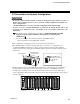
Input A
CT input B
Input A: Alarm output
CT input B: Heater break alarm output
Module channel numbers are automatically assigned from the left in order for each type of module.
IN1
IN2
H-PCP
H-TIO-D
H-
TIO-A
H-AI-B
H-AO-B
Channel No.
CH1 CH2 CH3
CH4
CH5 CH1
CH2
CH3
CH4
CH1
CH2
H-
TIO-B
OUT1
Heat
Cool
OUT2
Heat
Cool
IN3
IN4
IN5
OUT3
OUT4
OUT5
AI2
AI4
AI1
AI3
AO2
AO1
2 channels heat/cool type
(Double type)
2 channels type 1 channel type
Temperature control module Analog input
module
Analog output
module
Assign CT inputs and H-DO module alarm
outputs within the same control unit.
(Because all control inputs and outputs must be
closed within the same control unit.)
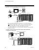
RS-422A
RS-422A
When the host computer connected:
Up to 16 control unit
When the operation panel is connected:
OPM, OPM-H, OPC, OPC-H: Up to 8 control unit
OPC-V06, OPC-V07: Up to 16 control unit
If two or more control units are multi-drop
connected, the communication specification of all
H-PCP modules must be RS-422A.