
Instruction manual


5. WIRING
IMSRM15-E6
98
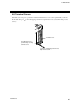
5.2 Wiring of Each Modules
For details on terminal configuration of each modules, refer to 3. DESCRIPTION OF
EACH MODULES (P. 28).
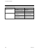
Re-confirmation of the specifications
Re-confirm the input/output specifications of each module.
In particular, take adequate care of the input current and voltage for the inputs, and the output current
and voltage for the outputs. If a voltage is applied or if a current flows exceeding the maximum
opening/closing capacity, this will cause the problems such as breakdowns, damage, fires, etc.
Cautions for wiring
Configure the wiring so that it will be easy to carry out the replacement of modules.
Confirm that each module is securely attached to the mother block.
Confirm that the terminal panels and connectors are securely attached to the modules.
Do not excessively tighten the terminal screws. In addition, use the solderless
terminal appropriate to the screw size.
Screw size:
Power supply terminals (H-PCP-A/B): M3×7
Input/Output terminals: M3×6 (with 5.8×8 square washer)
Recommended tightening torque: 0.4 N
m (4 kgf cm)
Applicable wire: Solid/twisted wire of 0.25 to 1.65 mm
2
Specified solderless terminals:
Power supply terminals (H-PCP-A/B): Circular terminal with isolation V1.25-3 *
Input/Output terminals: Circular terminal with isolation V1.25-MS3
Manufactured by J.S.T MFG CO., LTD.
* If solderless terminal lugs are used, a terminal cover is not kept.
Make sure that during field wiring parts of conductors can not come into
contact with adjacent conductive parts.
Leakage current at 24 V DC input
When a two-wire system sensor (proximity switch or photoelectric switch) or limit switch with LED is
used, the lamp may light due to leakage current or incorrect input.
No problem arises for a leakage current of less than 0.75 mA, but for 0.75 mA or more, connect a
bleeder resistor as shown in figure to lower the input impedance.
Two-wire system
sensor, etc.
Input power
supply
Bleeder resisto
r
DI module
41.6
10.4 I - 4
R =
k or smaller
2.3
R
W =
W or larger
I: Device leakage current
R: Bleeder resistance value (
)
W: Watt generated in bleeder resistor (W)
[Reference] The above equations are obtained from the following equations.
Input voltage (24)
R
Input voltage (2.3)
Input voltage (24)
R +
Input voltage (2.3)
I OFF voltage (4)
V1.25 MS3
V1.25
3
3.2 MIN
5.5 MAX
5.0
4 mm
9.0 mm
3.2 MIN
5.5 MAX
5.0
5.6 mm
9.0 mm