
Instruction manual


96
IMSRM15-E6
5. WIRING
5.1 Wiring Cautions
Power supply wiring
Use power supply as specified in power supply rated voltage range.
Power supply wiring must be twisted and have a low voltage drop.
Provide separate power supply for this instrument independent of other input/output circuits, motors,
equipment and operating circuits.
If there is electrical noise in the vicinity of the instrument that could affect operation, use a noise filter.
Shorten the distance between the twisted power supply wire pitches to achieve the most
effective noise reduction.
Always install the noise filter on a grounded panel.
Minimize the wiring distance between the noise filter output and the instrument power supply
terminals to achieve the most effective noise reduction.
Do not connect fuses or switches to the noise filter output wiring as this will reduce the
effectiveness of the noise filter.
Take into consideration the instrument power supply voltage and filter frequency
characteristics when selecting the most effective noise filter.
For an instrument with 24 V power supply, supply input, supply power from “SELV” circuit defined
as IEC 60950-1.
A suitable power supply should be considered in end-use equipment. The power supply must be in
compliance with a limited-energy circuits (maximum available current of 8 A).
To prevent electric shock or instrument failure, do not turn on the power until all
wiring is completed. Make sure that the wiring is correct before applying power
to the instrument.
WARNING
!
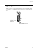
H-PCP module
*1: For 24 V DC type
*2: For 100 to 120 V AC/
200 to 240 V AC type
100 to 120 V AC
L (+)
N (
-
)
14
Breaker
13
12
Ground
Multi-drop connection
to the control unit
Power
supply
Other power supply
200 to 240 V AC
24 V DC
Insulaion
transformer *2
1:1
AC/DC
converter
*1
(Specify when
ordering)
15
11