
Specifications


®
RKC INSTRUMENT INC.
The first edition: JAN. 2005 [IMQ00]
The fifth edition: SEP. 2011 [IMQ00]
HEADQUARTERS: 16-6, KUGAHARA 5-CHOME, OHTA-KU TOKYO 146-8515 JAPAN
PHONE: 03-3751-9799 (+81 3 3751 9799) E-mail: info@rkcinst.co.jp
FAX: 03-3751-8585 (+81 3 3751 8585) Website: http://www.rkcinst.com/ SEP. 2011
CC-Link is a registered trademark of Mitsubishi Electric Co. Ltd.
Modbus is a registered trademark of Schneider Electric.
Company names and product names used in this manual are the trademarks or registered
trademarks of the respective companies.
2.3 Connection to PLC
Method to connect
The PLC (master station) and COM-JC make multi-drop connection in CC-Link
dedicated cable Ver. 1.10.
PLC
COM-JC
CC-Link dedicated cable
Ver.1.10
Up to 61 stations
Master station
Station to station
cable length:
20 cm or more
Termination
resistor
Termination
resistor
Up to 64 stations:
1 station occupied 1 time
Communication speed and maximum transmitter distance
Communication
speed
Station to station
cable length
Maximum transmitter distance
(maximum length of network)
10 Mbps
20 cm or more
100 m
5 Mbps 160 m
2.5 Mbps 400 m
625 kbps 900 m
156 kbps 1200 m
Terminal numbers and signal details
Terminal No. Signal name Symbol Cable color
1 Data A DA Blue
2 Data B DB White
3 Data ground DG Yellow
4 Shield SLD Grounding wire (Shield)
5 Frame ground FG ⎯
1: DA
2: DB
3: DG
4: SLD
5: FG
CC-Link connection terminals
Terminal screws
Screws size: M3
Recommended tightening torque: 0.4 N
x
m (4 kgf⋅cm)
The CC-Link connecting terminal cannot do on-line installation or
dismount for terminal block of dismount impossibility. The device
cannot be replaced unless the link is set offline. In addition, FG (frame
ground) terminal of terminal number 5 is FG in a CC-Link function, and
it is not FG of instrument all.
Ground both ends of the shield wire on the twisted pair cable via the
SLD or FG terminal of each module. In addition, the SLD terminal is
internally connected with the FG terminal.
Do not ground the instrument together with other equipment.
In addition, use grounding wires with a cross section of 2.0 mm
2
or
more. (Ground resistance: 100 ohm or less)
For cable specifications, connection method and vendor, refer to the
website of CC-Link Partner Association.
URL: http://www.cc-link.org/
Connection diagram
Always connect a termination resistor between the DA and DB
terminals of the module to be located at the far end.
Termination resistor: 110 Ω ± 5 % 1/2 W
DA
DB
DG
SLD
FG
DA
DB
DG
SLD
FG
DA
DB
DG
SLD
FG
TR
COM-JC
COM-JC
TR
CC-Link dedicated
cable Ver.1.10
Master station
CC-Link dedicated
cable Ver.1.10
TR: Termination resistor
2.4 Connection to the Controllers
Conduct wiring between the COM-JC and controller (FB100/400/900) as shown in the
following. (When conducting wiring to the FB100/400/900, always conduct wiring to
the Communication 1 terminal.)
Connection diagram
RS-485
y
y
y
FB400/900
FB400/900
Maxmum connections: 31 controllers
R2
R1: Internal termination resistor (120 Ω 1/2 W)
R2: Termination resistor for external connection
(Example: 120 Ω 1/2 W)
If communication errors occur frequently due to
the operation environment or the communication
distance, connect termination resistors.
25
T/R (B)
T/R (A)
26
27
SG
25
T/R (B)
T/R (A)
26
27
SG
COM-JC
T/R (A)
SG
T/R (B)
4
1
5
R1
Terminal base
Paired wire
Communication terminals
(communication 1 side)
Communication terminals
(communication 1 side)
(−)
(+)
(−)
(+)
(−)
(+)
Communication terminals of controller
(Communication 1 side)
Terminal No.
Symbol
FB100 FB400/900
13 25 SG
14 26 T/R (A)
15 27 T/R (B)
Shielded twisted
pair wire
• The cable and termination resistor for external connection must be
provided by the customer.
• The termination resistor existing within the COM-JC can be connected
or disconnected by the switch. (Factory set value: Termination resistor
connected)
2.5 System Configuration Example
Power supply (24 V DC)
CC-Link
CC-Link
Communication
converter
COM-JC
PLC
(Mitsubishi Electric
MELSEC Q se
r
ies
)
FB100, FB400 or FB900
(Up to 31 controllers)
FB100
FB400
FB900
1
FB100
FB400
FB900
2
FB100
FB400
FB900
31
Controller communication (RS-485: Modbus)
z Relationship between number of occupied station/extended cyclic and
number of controller connection
Number of occupied station/
extended cyclic
Number of maximum connection of
controller
1 station occupied 1 time 2 controllers
4 stations occupied 1 time 16 controllers
4 stations occupied 2 times 31 controllers
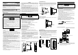
3. PARTS DESCRIPTION
Station number
setting switch
Indication
lamps
Terminal
cover
Front view Left side view
Terminal base
Mainframe
CC-Link communication
speed setting switch
Terminal
cover
Mounting
bracket
CC-Link
connection
terminals
(COM.PORT)
Dip switch
Indication
lamps
FAIL
RUN
SD
RD
z Indication lamps
FAIL [Red]
• When instrument abnormally: Turns on
• CC-Link setting error: Turns on
• CC-Link operation error: Flashes slowly
• CC-Link setting is changed: Flashes rapidly
RUN [Green]
• When normally: Turns on
• Operation error: Flashes slowly
• During controller communication initialization:
Flashes rapidly
SD [Green] During CC-Link data send: Turns on
RD [Green] During CC-Link data receive: Turns on
z CC-Link connection terminals
COM. PORT Terminals for PLC (Master) connection
z Switches
Station number setting
switch
Set the station number for CC-Link
CC-Link
communication speed
setting switch
Set the communication speed for CC-Link
Dip switch
• Set the number of occupied station/extension cyclic for
CC-Link
• Set the communication speed for controller
communication
z Others
Terminal cover Terminal covers above and below the COM-JC
Mounting bracket
• Used for the DIN rail mounting
• When panel mounted, two mounting brackets are required
for the upper and lower sides (one required for the upper
side: separately sold).
Terminal base
Part of the terminal and base of COM-JC
(There is the termination resistor transfer switch in the inside
of terminal base)
Mainframe Part of the mainframe of COM-JC
4. SPECIFICATIONS
CC-Link communication
Protocol: CC-Link Ver. 2.00/Ver. 1.10
Communication speed: 156 kbps, 625 kbps, 2.5 Mbps, 5 Mbps, 10 Mbps
Station number: 1 to 61 (4 stations occupied 1 time, 4 stations occupied 2 times)
1 to 64 (1 station occupied 1 time)
Connection cable: CC-Link dedicated cable Ver. 1.10
Number of occupied station/extended cyclic and CC-Link version:
CC-Link Ver. 1.10: 1 station occupied 1 time,
4 stations occupied 1 time
CC-Link Ver. 2.00: 4 stations occupied 2 times
Controller communication
Interface: Based on RS-485, EIA standard
Protocol: Modbus-RTU
Communication speed: 9600 bps, 19200 bps, 38400 bps
Data bit configuration: Data 8-bit, Without parity, Stop 1-bit
Maximum connections: 31 controllers (FB100/400/900)
General specifications
Power supply voltage: 24 V DC
Power supply voltage range:
21.6 V DC to 26.4 V DC
Power consumption: 120 mA max. (at 24 V DC)
Rush current: 12 A or less
Allowable ambient temperature range:
−10 to +50 °C
Allowable ambient humidity range:
5 to 95 %RH (Non condensing)
(Absolute humidity: MAX.W.C 29.3 g/m
3
dry air at 101.3 kPa)
Installation environment conditions:
Indoor use
Altitude up to 2000 m
Weight: Approx. 220 g
Standard
Safety standard: UL: UL61010-1
cUL: CAN/CSA-C22.2 No. 61010-1
CE marking: LVD: EN61010-1
EMC: EN61326-1
C-Tick: EN55011
5. MODEL CODE
COM- JC 01 -
(1) (2)
(1) Corresponding to the RKC temperature controller
01: FB100/400/900
(2) RUN/STOP logic selection
1: 0: RUN
1: STOP
2: 0: STOP
1: RUN
*